
Related Manuals for Ludlum Measurements 9-4


Summary of Contents for Ludlum Measurements 9-4
- Page 1 LUDLUM ION CHAMBER MODEL 9-4 USERS MANUAL June 2018 Serial Number 265751 and Succeeding Serial Numbers...
- Page 2 LUDLUM ION CHAMBER MODEL 9-4 USERS MANUAL June 2018 Serial Number 265751 and Succeeding Serial Numbers...
- Page 3 Ludlum Measurements, Inc. Copyright© 2013.
-
Page 4: Statement Of Warranty
RETURN OF GOODS TO MANUFACTURER If equipment needs to be returned to Ludlum Measurements, Inc. for repair or calibration, please send to the address below. All shipments should include documentation containing return shipping address, customer name, telephone number, description of service requested, and all other necessary information. -
Page 5: Safety Precautions
Caution - The operator or responsible body is cautioned that the protection provided by the equipment may be impaired if the equipment is used or handled in a manner not specified by Ludlum Measurements, Inc. Note – The operator or responsible body should give special attention to the information provided, as failure to do so may result in damage to the instrument or instrument failure. - Page 6 Visual images are used in this manual to convey the possible hazard associated with the operation, handling, or maintenance of the instrument. The following definitions are provided to describe these hazards; however, Ludlum Measurements cannot make any guarantees to the extent of the hazard posed.
-
Page 8: Table Of Contents
Figure 8 - Main Board Schematic (Page 4) .................................. Back of manual Figure 9 - Electrometer Board Layout (Front) ................................Back of manaul Figure 10 - Electrometer Board Schematic (Page 1) ..............................Back of manual Ludlum Measurements, Inc. June 2018... -
Page 9: Introduction
The Model 9-4 calibration kit allows the ability to calibrate for temperature and pressure. Temperature and pressure compensation thus allows the instrument to measure within 20% of the true value even when the temperature is varied from -20 to 50 °C (-4 to 122 °F), and within 15%, as... -
Page 10: Identification Of Controls And Functions
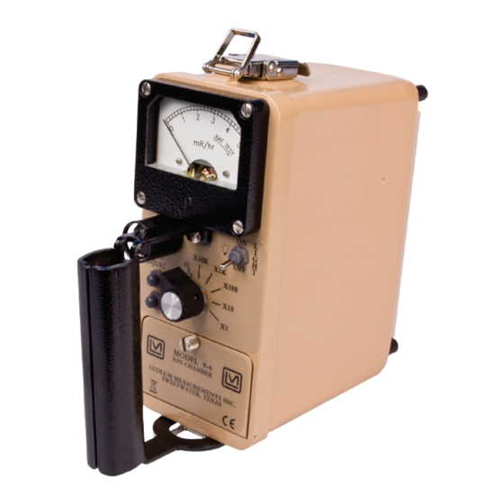
MODEL 9-4 Technical Manual Section 2 Section Identification of Controls and Functions : This is a six-position switch marked OFF, ×10K, Range Selector Switch ×1K, ×100, ×10, and ×1. Turning the range selector switch from to one of the range multiplier positions (×10K, ×1K, ×100, ×10, and ×1) provides the operator with an overall range of 0 to 50,000 mR/hr. -
Page 11: Getting Started
Instrument Configuration The Model 9-4 has two options for chamber wall voltage. An internal jumper may be selected to maintain voltage on the chamber wall with the instrument turned off. This option allows a faster, three-minute settling time when the instrument is frequently used. -
Page 12: Battery Installation
×1 scale to settle within 0.1 mR/hr. Battery Installation Ensure the Model 9-4 range selector switch is in the OFF position. Open the battery lid by pushing down and turning the quarter-turn thumbscrew counterclockwise a quarter of a turn. Install two “D” size batteries in the compartment. -
Page 13: Battery Test
MODEL 9-4 Technical Manual Section 3 Figure 2 - Battery Door Internal Markings Note the (+) and (-) marks inside the battery holder (see Figure 2 - Battery Door Internal Markings). Match the battery polarity to these marks. Insert both batteries to match these marks. Close the battery box lid, then push down and turn the quarter-turn thumb screw clockwise a quarter of a turn. - Page 14 MODEL 9-4 Technical Manual Section 3 Turn the instrument range switch to the ×1 position. As the selector switch moves from the ×100 to ×10 a meter transient will occur. This transient is caused by an internal range relay and is normal.
-
Page 15: Technical Theory Of Operation
MODEL 9-4 Technical Manual Section 4 Section Technical Theory of Operation Chamber The chamber housing is constructed from acrylic and is coated inside and outside with carbon. The internal wall is maintained at approximately -90 volts. The external wall is at guard potential (approximately 1.5 volts). -
Page 16: Range Change
MODEL 9-4 Technical Manual Section 4 Range Change When the instrument is switched to the ×100, ×1K, or ×10K range, RL1 is closed, reducing the feedback resistance to approximately 4.2 x 10 ohms. At 500 mR/hr on the x100 range, the chamber current will be... -
Page 17: Range Calibration
MODEL 9-4 Technical Manual Section 4 Range Calibration Full-scale voltage for the electrometer output, pin 4 of U1 (electrometer board 5293-711) is approximately +0.03 volts for the ×1 range; 0.3 volts for the ×10 range; +0.03 volts for the ×100; and +0.3 volts for the ×1K range. -
Page 18: Power Supplies
MODEL 9-4 Technical Manual Section 4 Power Supplies Six voltages are provided for instrument operation. U108 and associated components generate -90 volts for chamber wall voltage. The supply will run continually with the instrument off if the jumper is placed between pins 1 and 2 of JP100. If the operator chooses to have wall voltage off with the instrument switched off, then the jumper should be moved to pins 2 and 3 of JP100. -
Page 19: Cleaning And Maintenance
Precautions Instrument maintenance consists of keeping the instrument clean and periodically checking the batteries, desiccants, and calibration. The Model 9-4 (excluding chamber window) may be cleaned externally with a damp cloth, using only water as the wetting agent. Do not immerse the instrument in any liquid. -
Page 20: Storage
MODEL 9-4 Technical Manual Section 5 Ludlum Measurements offers a full-service repair and calibration department. We not only repair and calibrate our own instruments, but also most other manufacturers’ instruments. Calibration procedures are available upon request for customers who choose to calibrate their own instruments. - Page 21 MODEL 9-4 Technical Manual Section 5 Repeat until the box and desiccant appear dry. When fully dried out, the desiccant will be blue in color. The desiccant box may be HOT when removed from the microwave or oven! Please use caution so as to avoid burning your skin.
-
Page 22: Specifications
MODEL 9-4 Technical Manual Section 6 Section Specifications : reading within 10% of true value Linearity : 0-500 mSv/h (0-50,000 mR/hr) Range Chamber : carbon-coated acrylic Chamber Wall Construction : 220 cm (13.4 in Chamber Volume : 7 mg/cm metallized polyester... - Page 23 MODEL 9-4 Technical Manual Section 6 : approximately five seconds for 90% of final meter deflection on Response the ×1 and ×10 scales, and three seconds on the ×100, ×1K, and ×10K scales : For the ×1 scale and if the wall voltage option is on with the Warm-up Time instrument off, the scale will settle within 0.1 mR/hr within three minutes.
- Page 24 MODEL 9-4 Technical Manual Section 6 Degree 3 (as defined by IEC 664) (Due to condensation, Pollution: conductive pollution or dry nonconductive pollution that becomes conductive occurs. This is found in industrial environments or construction sites, considered harsh environments.) : two “D” cell batteries housed in a sealed externally accessible...
-
Page 25: Recycling
To this end, Ludlum Measurements, Inc. strives to supply the consumer of its goods with information regarding reuse and recycling of the many different types of materials used in its products. -
Page 26: Parts List
MODEL 9-4 Technical Manual Section 8 Section Parts List The following parts are included with the Model 9-4 Five-Range Ion Chamber (Part Number 48-3739) Reference Description Part Number Figures 1 and 4 Model 9-4 Ion Chamber 4293-646 Model 9-4 Ion... -
Page 27: Main Circuit Board , Drawing 293 X 711
MODEL 9-4 Technical Manual Section 8 The Model 9-4 Five-Range Ion Chamber w/Case (Part Number 48-3701) includes all the parts included with the 48-3739 as well as the following: Storm CS-DSI-iM2300 2311063 Storm Case Medium Black Main Circuit Board, BOARD Completely Assembled Drawing 293 ×... - Page 28 MODEL 9-4 Technical Manual Section 8 Reference Description Part Number U105 LT1304CS8-5 06-6434 U106 LT1790BIS6-2.5 06-6691 U107 LMC7111BIM5X 06-6410 U108 LT1617ES5-1 06-6760 U109 SM5420-030-A-P-T 2311127 U110 PIC18LF2520-I/SO 06-6696 U111 INA126UA 06-6726 U112 MCP4822-E/SN 06-6722 U113 MCP9800AOT-M/OTG 06-6687 U114 MAX809JTRG 06-6423...
- Page 29 MODEL 9-4 Technical Manual Section 8 R126 10M, 250mW, 1% 12-7996 R128 750K, 250mW, 1% 12-7882 R130 10M, 250mW, 1% 12-7996 R131 3.01M, 250mW, 1% 12-720 R134 100K, 250mW, 1% 12-7834 R135 221K, 250mW, 1% 12-7845 R136 10K, 250mW, 1%...
-
Page 30: Electrometer Board , Drawing 293 X 670
MODEL 9-4 Technical Manual Section 8 Electrometer Board, BOARD Completely Assembled Drawing 293 × 670 Electrometer Board 5293-442 CAPACITORS 2pF, 200V 04-5726 INTEGRATED IC-LMP7721MA 06-6728 CIRCUIT DIODES CR1-CR2 CMPSH-3 07-6489 RESISTORS 1M, 1/4W, 1% 12-7844 500G, 330mW, 20% 12-7248 4.2G, 1W, 10%... -
Page 31: Drawings
MODEL 9-4 Technical Manual Section 9 Section Drawings MAIN BOARD SCHEMATIC, Drawing 293 × 711 (4 Sheets) MAIN BOARD LAYOUT 293 × 712 (2 Sheets) ELECTROMETER BOARD, Drawing 293 × 670 ELECTROMETER BOARD LAYOUT 293 × 672 Ludlum Measurements, Inc.
Need help?
Do you have a question about the 9-4 and is the answer not in the manual?
Questions and answers