Sierra Innova-Mass 240-V Instruction Manual
Multi-parameter vortex mass flow meters
Hide thumbs
Also See for Innova-Mass 240-V:
- Instruction manual (146 pages) ,
- Instruction manual (20 pages) ,
- Instruction manual (14 pages)
Table of Contents
Advertisement
Quick Links
Series 240/241 Instruction Manual
Table of Contents
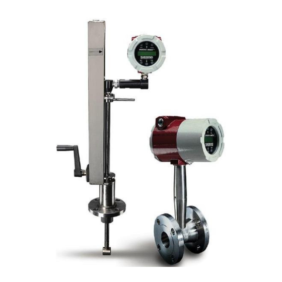
Sierra Series 240 and 241
Innova-Mass™ Multi-Parameter
Vortex Mass Flow Meters
Models 240- V and 241-V
Instruction Manual
Part Number: IM-24, Rev. E 11/10
IMPORTANT: This manual is for use with 240/241 Vortex Products
purchased February 2008 or later
IM-24
0-1
Advertisement
Table of Contents
Troubleshooting

Related Manuals for Sierra Innova-Mass 240-V


Summary of Contents for Sierra Innova-Mass 240-V
- Page 1 Series 240/241 Instruction Manual Table of Contents Sierra Series 240 and 241 Innova-Mass™ Multi-Parameter Vortex Mass Flow Meters Models 240- V and 241-V Instruction Manual Part Number: IM-24, Rev. E 11/10 IMPORTANT: This manual is for use with 240/241 Vortex Products...
- Page 2 Unless you have specifically ordered Sierra’s optional O cleaning, this flow meter may not be fit for oxygen service. Sierra Instruments, Inc., is not liable for any damage or personal in- jury, whatsoever, resulting from the use of Sierra Instruments standard mass flow meters for oxygen gas.
-
Page 3: Table Of Contents
Series 240/241 Instruction Manual Table of Contents Table of Contents Chapter 1 Introduction ™ Innova-Flo Vortex Flow Meters ............1-1 Using this Manual ................. 1-1 Note and Safety Information ............1-2 Receipt of System Components ............ 1-2 Technical Assistance ..............1-2 How the Innova-Flo Vortex Flow Meter Operates ...... - Page 4 Table of Contents Series 240/241 Instruction Manual Calibration Menu ................3-9 Password Menu ................3-10 Chapter 4 HART Communications Wiring ....................4-1 HART Menus ..................4-2 Fast Key Sequence ................4-3 Fast Key Sequence (continued) ............4-4 Chapter 5 Troubleshooting and Repair Hidden Diagnostics Menus ..............
- Page 5 Always remove main power before disassembling any part of the mass flow meter. Caution! Calibration must be performed by qualified personnel. Sierra Instruments, Inc., strongly re- commends that you return your flow meter to the factory for calibration. In order to achieve accurate and repeatable performance, the flow meter must be in- stalled with the specified minimum length of straight pipe upstream and downstream of the flow meter’s sensor head.
-
Page 6: Chapter 1 Introduction
Chapter 1 Introduction Chapter 1 Introduction Innova-Flo™ Vortex Flow Meters The Sierra Instruments’ Series 240 In-Line and the Series 241 Insertion Innova-Flo™ Vortex Flow Meters provide a reliable solution for process flow measurement. From a single entry point in the pipeline, Innova-Flo meters offer precise measurements of mass or volumetric flow. -
Page 7: Note And Safety Information
Receipt of System Components When receiving a Sierra flow meter, carefully check the outside packing carton for damage incurred in shipment. If the carton is damaged, notify the local carrier and submit a report to the factory or distributor. Remove the packing slip and check that all ordered components are present. -
Page 8: How The Innova-Flo Vortex Flow Meter Operates
How the Innova-Flo Vortex Flow Meter Operates Figure 1-1. Series 240 In-Line Vortex Flow Meter ™ Sierra Series 240 and 241 Innova-Flo Vortex Flow Meters use a unique velocity sensor head to monitor volumetric flow rate. The built-in flow computer calculates mass flow rate based on a constant value of fluid density stored in the instrument’s memory. - Page 9 Chapter 1 Introduction Series 240/241 Instruction Manual Vortex Shedding Frequency Von Karman vortices form downstream of a shedder bar into two distinct wakes. The vortices of one wake rotate clockwise while those of the oth- er wake rotate counterclockwise. Vortices generate one at a time, alter- nating from the left side to the right side of the shedder bar.
- Page 10 Series 240/241 Instruction Manual Chapter 1 Introduction Flow Velocity Range To ensure trouble-free operation, vortex flow meters must be correctly sized so that the flow velocity range through the meter lies within the measurable velocity range (with acceptable pressure drop) and the linear range.
- Page 11 Chapter 1 Introduction Series 240/241 Instruction Manual ™ As shown below, Innova-Flo Vortex Flow Meters exhibit a constant Strouhal number across a large range of Reynolds numbers, indicating a consistent linear output over a wide range of flows and fluid types. Be- low this linear range, the intelligent electronics in Innova-Flo automati- cally corrects for the variation in the Strouhal number.
-
Page 12: Flow Meter Configurations
Series 240/241 Instruction Manual Chapter 1 Introduction Flow Meter Configurations Innova-Flo™ Vortex Flow Meters are available in two configurations: • Series 240 in-line flow meter (replaces a section of the pipeline) • Series 241 insertion flow meter (requires a “cold” tap or a “hot” tap into an existing pipeline) Both the in-line and insertion configurations are similar in that they both use identical electronics and have similar sensor heads. - Page 13 Chapter 1 Introduction Series 240/241 Instruction Manual The meter includes a local 2 x 16 character LCD display housed within the enclosure. Local operation and reconfiguration is accomplished using six push buttons. For hazardous locations, the six push buttons can be operated through the sealed enclosure using a hand-held magnet, thereby not compromising the integrity of the hazardous location certification.
-
Page 14: Chapter 2 Installation
Series 240/241 Instruction Manual Chapter 2 Installation Chapter 2 Installation Installation Overview Innova-Flo™ meter installations are simple and straightforward. Both the Se- ries 240 In-Line and Series 241 Insertion type flow meter installations are covered in this chapter. After reviewing the installation requirements given below, see page 2-3 for Series 240 installation instructions. -
Page 15: Unobstructed Flow Requirements
Chapter 2 Installation Series 240/241 Instruction Manual Unobstructed Flow Requirements Select an installation site that will minimize possible distortion in the flow profile. Valves, elbows, control valves and other piping components may cause flow disturbances. Check your specific piping condition against the ex- amples shown below. -
Page 16: Series 240 In-Line Flow Meter Installation
Series 240/241 Instruction Manual Chapter 2 Installation Series 240 In-Line Flow Meter Installation Install the Series 240 In-Line Flow Meter between two conventional pipe flanges as shown in Figures 2-3 and 2-4. Table 2-1 provides the recommend- ed minimum stud bolt lengths for wafer-style meter body size and different flange ratings. -
Page 17: Wafer-Style Flow Meter Installation
Chapter 2 Installation Series 240/241 Instruction Manual Wafer-Style Flow Meter Installation Install the wafer-style meter between two conventional pipe flanges of the same nominal size as the flow meter. If the process fluid is a liquid, make sure the meter is located where the pipe is always full. This may require lo- cating the meter at a low point in the piping system. -
Page 18: Flange-Style Flow Meter Installation
Series 240/241 Instruction Manual Chapter 2 Installation Flange-Style Flow Meter Installation Install the flange-style meter between two conventional pipe flanges of the same nominal size as the flow meter. If the process fluid is a liquid, make sure the meter is located where the pipe is always full. This may require lo- cating the meter at a low point in the piping system. -
Page 19: Series 241 Insertion Flow Meter Installation
Chapter 2 Installation Series 240/241 Instruction Manual Series 241 Insertion Flow Meter Installation Prepare the pipeline for installation using either a cold tap or hot tap method described on the following pages. Refer to a standard code for all pipe tap- ping operations. -
Page 20: Cold Tap Guidelines
Series 240/241 Instruction Manual Chapter 2 Installation Cold Tap Guidelines Refer to a standard code for all pipe tapping operations. The following tap- ping instructions are general in nature and intended for guideline purposes only. Caution! 1. Turn off the flow of process gas, liquid or steam. Verify that the line is When using toxic or not pressurized. -
Page 21: Hot Tap Guidelines
Chapter 2 Installation Series 240/241 Instruction Manual Hot Tap Guidelines Refer to a standard code for all pipe tapping operations. The following tap- ping instructions are general in nature and intended for guideline purposes Warning! only. Hot tapping must be performed by a trained 1. -
Page 22: Flow Meter Insertion
Series 240/241 Instruction Manual Chapter 2 Installation Flow Meter Insertion The sensor head must be properly positioned in the pipe. For this reason, it is important that insertion length calculations are carefully followed. A sensor probe inserted at the wrong depth in the pipe will result in inaccurate readings. Insertion flow meters are applicable to pipes 2 inch and larger. -
Page 23: Installing Meters With A Compression Connection
Chapter 2 Installation Series 240/241 Instruction Manual Installing Flow Meters with a Compression Connection* Use the following formula to determine insertion length for flow meters (NPT and flanged) with a compression process connection. The installation procedure is given on the next page. Insertion Length Formula I = S –... - Page 24 Series 240/241 Instruction Manual Chapter 2 Installation Insertion Procedure for Meters with a Compression Connection Figure 2-7. Flow Meter with Compression Type Fitting 1. Calculate the required sensor probe insertion length. 2. Fully retract the stem until the sensor head is touching the bottom of the stem housing.
-
Page 25: Installing Meters With A Packing Gland Connection
Chapter 2 Installation Series 240/241 Instruction Manual Installing Flow Meters with a Packing Gland Connection* Use the formula below to determine the insertion depth for flow meters (NPT and flanged) equipped with an insertion tool. To install, see the next page for instructions for meters with a permanent insertion tool. - Page 26 Series 240/241 Instruction Manual Chapter 2 Installation Insertion Procedure for Flow Meters with Permanent Insertion Tool Figure 2-9. Flow Meter with Permanent Insertion Tool 1. Calculate the required sensor probe insertion length (see previous page). Measure from the depth marker arrow down the stanchion and scribe a mark at the calculated insertion depth.
- Page 27 Chapter 2 Installation Series 240/241 Instruction Manual Insertion Procedure for Flow Meters with Removable Insertion Tool Figure 2-10. Flow Meter with Removable Insertion Tool 1. Calculate the required sensor probe insertion length. Measure from the depth marker arrow down the stanchion and scribe a mark at the calcu- lated insertion depth.
- Page 28 Series 240/241 Instruction Manual Chapter 2 Installation 7. Tighten the packing gland nuts to stop leakage around the stem. Do not torque over 20 ft-lbs. 8. Slide the stem clamp back into position. Torque stem clamp bolts to 15 ft-lbs. Replace the stem clamp nuts and torque to 10-15 ft-lbs. 9.
- Page 29 Chapter 2 Installation Series 240/241 Instruction Manual Insertion Procedure for Flow Meters with No Insertion Tool (Packing Gland Connection) 1. Calculate the required sensor probe insertion length. Warning! 2. Fully retract the stem until the sensor head is touching the bottom of the The line must be stem housing.
-
Page 30: Adjusting Meter Orientation
Series 240/241 Instruction Manual Chapter 2 Installation Adjusting Meter Orientation Depending on installation requirements, you may need to adjust the meter orientation. There are two adjustments available. The first rotates the position of the LCD display/keypad and is available on both in-line and insertion me- ters. -
Page 31: Enclosure Adjustment
Chapter 2 Installation Series 240/241 Instruction Manual Enclosure Adjustment (Series 240 Only) Figure 2-13. Enclosure Viewing Adjustment To avoid damage to the sensor wires, do not rotate the enclosure beyond 180- degrees from the original position. To adjust the enclosure: 1. -
Page 32: Wiring Connections
Series 240/241 Instruction Manual Chapter 2 Installation Wiring Connections The NEMA 4X enclosure contains an integral wiring compartment with one dual strip terminal block (located in the smaller end of the enclosure). Two Warning! 3/4-inch female NPT conduit entries are available for separate power and To avoid potential electric signal wiring. - Page 33 Chapter 2 Installation Series 240/241 Instruction Manual 4-20 mA Output Connections The Innova-Flo meter has a single 4-20 mA loop. The 4-20 mA loop current is controlled by the meter electronics. The electronics must be wired in series with the sense resistor or current meter. The current control electronics re- quire 12 volts at the input terminals to operate correctly.
-
Page 34: Pulse Output Connections
Figure 2-16. Isolated Pulse Output with External Power Supply Optional Backlight Connection The Sierra Model 240 has an optional backlight connection provided. It is in- tended to be powered by a separate 12 to 36 VDC power supply or by the pulse power input. -
Page 35: Remote Electronics Wiring
Chapter 2 Installation Series 240/241 Instruction Manual Remote Electronics Wiring The remote electronics enclosure should be mounted in a convenient, easy to reach location. For hazardous location installations, make sure to observe agency requirements for installation. Allow some slack in the interface cable between the junction box and the remote electronics enclosure. -
Page 36: Chapter 3 Operating Instructions
Press ENTER to continue. (If change is not alllowed, ENTER has no effect.) All outputs are disabled when using the Setup Menus. SIERRA INSTRUMENTS The EXIT key is active within the Setup Menus. When using a Setup Menu, EXIT returns you to the Run Mode. -
Page 37: Start Up
Chapter 3 Operation Series 240/241 Instruction Manual Start-Up To begin flow meter operation: 1. Verify the flow meter is installed and wired as described in Chapter Note Starting the flow meter or pressing EXIT will 2. Apply power to the meter. At start up, the unit runs a series of self- always display the Run tests that check the program configuration and all flow sensing com- Mode screens. -
Page 38: Using The Setup Menus
Series 240/241 Instruction Manual Chapter 3 Operation Using the Setup Menus Run Mode Screens ENTER Mass Flow Password Rate Setup Menus Volume ENTER Flow Rate Output Display Totalizer Units Diagnostics Calibration Password Menu Menu Menu Menu Menu Menu Menu Total 4-20 mA Cycle Time Mass Flow... -
Page 39: Output Menu
Chapter 3 Operation Series 240/241 Instruction Manual Output Menu ENTER Run Mode Password ENTER Output Menu keys to access menus < Measure > 4-20mA Output 1 None < 4mA = xxxx > < 20mA = xxxx > < TimeConst (sec) More >... -
Page 40: Display Menu
Series 240/241 Instruction Manual Chapter 3 Operation Display Menu ENTER Run Mode Password ENTER Display Menu keys to access menus Cycle Time(sec) If Cycle Time is set to zero, manual advance is required Number of Digits Used to set the number of digits displayed after decimal point Display TC(sec) TC = Display Time Constant, used to smooth display... -
Page 41: Totalizer Menu
Chapter 3 Operation Series 240/241 Instruction Manual Totalizer Menu ENTER Run Mode Password ENTER Totalizer Menu keys to access menus Totaling Example: Inactive Mass Volume Maximum flowrate = 600 gallons per minute (600 gallons per minute = 10 gallons per second) (unit)/Pulse xxxx If unit per pulse is set to 600 gallons per pulse,... -
Page 42: Units Menu
Series 240/241 Instruction Manual Chapter 3 Operation Units Menu ENTER Run Mode Password ENTER Units Menu keys to access menus Mass Flow Unit lb = pounds Ston = 2000 pounds Ston Lton = 2240 pounds Lton gram = grams gram kg = 1000 grams Mton = Metric Ton = 1000 kg Mton... -
Page 43: Diagnostics Menu
Chapter 3 Operation Series 240/241 Instruction Manual Diagnostics Menu ENTER Run Mode Password ENTER Diagnostics Menu keys to access menus Sim Vor Freq Simulate Vortex Frequency (Hz) Highest Velocity Highest Recorded Velocity (ft/sec) Use the Diagnostics Menu to simulate flow and review the highest recorded veloci- ty in ft/sec. -
Page 44: Calibration Menu
Series 240/241 Instruction Manual Chapter 3 Operation Calibration Menu ENTER Run Mode Password ENTER Calibration Menu keys to access menus Meter Size Series 220 - meter size or Pipe ID Series 221 - pipe internal diameter (inches) Meter calibration constant Meter Factor Series 220 - pulses/ft xxxx... -
Page 45: Password Menu
Chapter 3 Operation Series 240/241 Instruction Manual Password Menu ENTER Run Mode Password ENTER Password Menu keys to access menus Set Password 1234 Use the Password Menu to set or change the system password. The factory-set password is 1234. 3-10 IM-24... -
Page 46: Chapter 4 Hart Communications
Series 240/241 Instruction Manual Chapter 4 HART Communications Chapter 4 HART Communications Wiring The diagram below details the proper connections required for HART communi- cations: Warning! Place controls in manual mode when making con- figuration changes to the vortex meter. IM-24... -
Page 47: Hart Menus
Chapter 4 HART Communications Series 240/241 Instruction Manual HART Menus Online Menu 1 Device Setup 1 Process Variables 1 Snsr 1 4 mA 2 PV 2 AI % Rnge 2 20 mA 3 PV AO 3 AO1 3 Other 1 4 mA 4 End 2 20 mA 1 Test Device... -
Page 48: Fast Key Sequence
Series 240/241 Instruction Manual Chapter 4 HART Communications Fast Key Sequence Use password 16363. Sequence Description Access Notes 1,1,1 Snsr View Primary variable value 1,1,2 AI % Rnge View Analog output % range 1,1,3 View Analog output, mA 1,2,1 Test Device Not used 1,2,2,1 4 mA... - Page 49 Chapter 4 HART Communications Series 240/241 Instruction Manual Sequence Description Access Notes 1,4,3,1,3,1 4 mA View Loop test, fix analog output at 4 mA 1,4,3,1,3,2 20 mA View Loop test, fix analog output at 20 mA 1,4,3,1,3,3 Other Edit Loop test, fix analog output at mA value entered 1,4,3,1,3,4 Exit loop test 1,4,3,1,4...
-
Page 50: Chapter 5 Troubleshooting And Repair
Series 240/241 Instruction Manual Chapter 5 Troubleshooting & Repair Chapter 5 Troubleshooting and Repair 4-20(1),Zero xxxx 4-20(1),FScale xxxx Reynolds Corr. Gain Control Filter Control Adj. Filter Factory Defaults xx dB Meter Type Pulse Out Queue Test Pulse Out xxxxxxxxxx Sig. Rev Micro Rev Spi Err Sent... -
Page 51: Column One Hidden Diagnostics Values
Chapter 5 Troubleshooting & Repair Series 240/241 Instruction Manual Column One Hidden Diagnostics Values • f = vortex shedding frequency (Hz). If an asterisk (*) is dis- played after the f value, a valid vortex signal is being registered for the flow. •... -
Page 52: Column Two Hidden Diagnostics Values
Series 240/241 Instruction Manual Chapter 5 Troubleshooting & Repair • Pulse Out Queue = Pulse output queue. This value will ac- cumulate if the totalizer is accumulating faster than the pulse output hardware can function. The queue will allow the pulses to “catch up”... -
Page 53: Troubleshooting The Flow Meter
Chapter 5 Troubleshooting & Repair Series 240/241 Instruction Manual agnostics) and then actuate the enter key twice. This action will cause the meter to output its 4 mA or 20 mA condition. If the DVM indicates a current greater than ± 0.006 mA from 4 or 20, adjust the setting up or down until the output is calibrated. -
Page 54: Symptom: No Output
Series 240/241 Instruction Manual Chapter 5 Troubleshooting & Repair tice, the Ck value controls the adaptive filter, fi, setting. During flow, view the f and fi values in the first column of the hidden diag- nostics. The fi value should be approximately 25 % higher than the f value. -
Page 55: Electronics Assembly Replacement
Chapter 5 Troubleshooting & Repair Series 240/241 Instruction Manual Electronics Assembly Replacement (All Meters) The electronics boards are electrostatically sensitive. Wear a grounding wrist strap and make sure to observe proper handling precautions re- quired for static-sensitive components. 1. Turn off power to the unit. 2. -
Page 56: Returning Equipment To The Factory
Series 240/241 Instruction Manual Chapter 5 Troubleshooting & Repair Returning Equipment to the Factory Before returning any Innova-Flo meter to the factory, you must re- quest a Return Material Authorization (RMA) number. To obtain an RMA number and the correct shipping address, contact Customer Ser- vice at: (800) 866-0200 or (831) 373-0200 in the USA, or +31(0)20-6145810 in Europe. -
Page 57: Appendix A Product Specifications
Series 240/241 Instruction Manual Appendix A Specifications Appendix A Product Specifications Accuracy Process 240 Series In-Line Meters 241 Series Insertion Meters Variables Liquids Gas & Steam Liquids Gas & Steam Volumetric ±0.7% of rate ±1% of rate ±1.2% of ±1.5% of rate Flow Rate over a over a... - Page 58 Appendix A Specifications Series 240/241 Instruction Manual Water Minimum and Maximum Flow Rates ½-inch ¾-inch 1-inch 1.5-inch 2-inch 3-inch 4-inch 6-inch 8-inch 1076 2437 4270 Linear Range Smart electronics corrects for lower flow down to a Reynolds num- ber of 5,000. The Reynolds number is calculated using the fluid density and viscosity entered into the memory.
- Page 59 Series 240/241 Instruction Manual Appendix A Specifications Power Requirements Loop powered, 12 to 36 VDC. Output Signals Analog: field rangeable linear, 4-20 mA output signal, 1000 ohms maximum loop resistance, selected by user for volumetric flow rate or mass flow rate. Pulse: field rangeable volume/pulse output for totalization is a 50- millisecond duration pulse operating a solid-state relay capable of switching 40 VDC, 40 mA maximum.
-
Page 60: Appendix B Glossary
Series 240/241 Instruction Manual Appendix B Glossary Appendix B Glossary A B C D Cross sectional area. acfm Actual cubic feet per minute (volumetric flow rate). ASME American Society of Mechanical Engineers. Bluff Body A non-streamlined body placed into a flow stream to create vortices. - Page 61 Appendix B Glossary Series 240/241 Instruction Manual I J K L In-Line Flow Meter A flow meter which includes a short section of piping which is put in-line with the user’s piping. Insertion Flow Meter A flow meter which is inserted into a hole in the us- er’s pipeline.
- Page 62 Series 240/241 Instruction Manual Appendix B Glossary Q R S T Flow rate, usually volumetric. Rangeability Highest measurable flow rate divided by the lowest measurable flow rate. Reynolds Number A dimensionless number equal to the density of a fluid or Re times the velocity of the fluid times the diameter of the fluid channel, divided by the fluid viscosity (i.e., Re = ρVD/μ).
- Page 63 Ex d IIB + H2 T6 Ex tD A21 IP66 T85°C IECEx KEM 08.0028 MANUFACTURED BY: Sierra Instruments 5 Harris Court, Building L Monterey, CA 93940 NOTE: The DATE of manufacture is included in the Serial Number Field. Example: XXXXXX-XXXX-yyyy; 101486-2391-2009 would indicate Serial Number 101486-2391 manufactured in 2009.
Need help?
Do you have a question about the Innova-Mass 240-V and is the answer not in the manual?
Questions and answers