Table of Contents
Advertisement
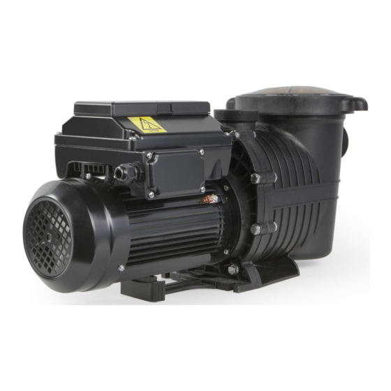
1.5HP 220V VARIABLE SPEED IN GROUND POOL PUMP
ITEM: 75021
OWNER'S MANUAL AND SAFETY INSTRUCTIONS
SAVE THIS MANUAL: KEEP THIS MANUAL FOR SAFETY WARNINGS, PRECAUTIONS, ASSEMBLY,
OPERATING, INSPECTION, MAINTENANCE AND CLEANING PROCEDURES. WRITE THE PRODUCT'S
SERIAL NUMBER ON THE BACK OF THE MANUAL NEAR THE ASSEMBLY DIAGRAM (OR MONTH
AND YEAR OF PURCHASE IF PRODUCT HAS NO NUMBER).
FOR QUESTIONS PLEASE CALL OUR CUSTOMER SUPPORT: (909) 628 0880 MON-FRI 9AM TO 3PM PST
Advertisement
Table of Contents

Related Manuals for Xtreme Power 75021


Summary of Contents for Xtreme Power 75021
- Page 1 1.5HP 220V VARIABLE SPEED IN GROUND POOL PUMP ITEM: 75021 OWNER’S MANUAL AND SAFETY INSTRUCTIONS SAVE THIS MANUAL: KEEP THIS MANUAL FOR SAFETY WARNINGS, PRECAUTIONS, ASSEMBLY, OPERATING, INSPECTION, MAINTENANCE AND CLEANING PROCEDURES. WRITE THE PRODUCT’S SERIAL NUMBER ON THE BACK OF THE MANUAL NEAR THE ASSEMBLY DIAGRAM (OR MONTH AND YEAR OF PURCHASE IF PRODUCT HAS NO NUMBER).
-
Page 2: Important Safety Information
IMPORTANT SAFETY INFORMATION GENERAL SAFETY WARNINGS Read all safety warnings and instructions. Failure to follow the warnings and instructions may result in electric shock, fire and/or serious injury. Save all warnings and instructions for future reference. SAFETY The warnings, precautions, and instructions discussed in this instruction manual cannot cover all possible conditions and situations that may occur. - Page 3 IMPORTANT SAFETY INFORMATION To reduce the risk of electric shock replace damaged cord immediately. DO NOT bury cord. Locate cord to prevent abuse from lawn mowers, hedge trimmers and other equipment. Risk of Electric Shock. Connect only to a branch circuit protected by a ground-fault circuit-interrupter (GFCI).
- Page 4 IMPORTANT SAFETY INFORMATION Hazardous Pressure: Pool and spa water circulation systems operate under hazardous pressure during start-up, normal operation, and after pump shut-off. Stand clear of circulation system equipment during pump start-up. Failure to follow safety and operation instructions could result in violent separation of the pump housing and cover due to pressure in the system, which could cause property damage, severe personal injury, or death.
- Page 5 DIAGRAM AND SPECIFICATIONS STRAINER BASKET DIGITAL CONTROL INTERFACE Assembled Product Dimensions (L x W x H) 22.00 x 9.90 x 11.60 Inches FEATURES AND SPECIFICATIONS Compatible with DE, sand, and cartridge filter Self-priming for in-ground functionality 1.5 HP In-Ground Pump Can be installed as 230v with 4 speed setting.
- Page 6 DIGITAL CONTROL INTERFACE...
-
Page 7: Stopping And Starting The Pump
DIGITAL CONTROL INTERFACE LED: On: Green light when pump is powered on. Warning: On if warning condition is present. Alarm: Red LED on if alarm condition occurs. Control Panel LCD Screen: • Line 1: Key icon indicates password protection mode is active. If password protect is not enabled, no key icon is displayed. - Page 8 DIGITAL CONTROL INTERFACE OPERATOR CONTROL PANEL: PUMP MENU GUIDE...
- Page 9 DIGITAL CONTROL INTERFACE SET DATE AND TIME The time controls all scheduled times, functions, and programmed cycles and stores the correct time for up to 96 hours after power is turned off. Reset if the power is off longer than 96 hours. 1.
-
Page 10: Set Control Panel Language
DIGITAL CONTROL INTERFACE SET CONTROL PANEL LANGUAGE To access the language menu: 1. Check that the green power LED is on. 2. Press Menu and press Select to select “Settings”. 3. Use the Up or Down arrows and scroll to “Device” and press Select. 4. -
Page 11: Pump Operating Modes
DIGITAL CONTROL INTERFACE Entering Password 1. Press any button (besides the speed button) to prompt the screen for a password. 2. To enter password, use the “Speed” button to input the number 1-4 and then press the Enter button to confirm. -
Page 12: Set Speeds 1-8 In Schedule Mode
DIGITAL CONTROL INTERFACE SET SPEEDS IN EGG-TIMER MODE (SPEEDS 1-4 ONLY) 1. Press Menu. 2. Use Up or Down arrows to scroll to “Speed 1-8”, then press Select. 3. Use Up or Down arrow to find the speed (1-4) you wish to program, then press Select. 4. -
Page 13: Time Out Control
DIGITAL CONTROL INTERFACE TIME OUT CONTROL The Time Out feature keeps the pump from running it’s programmed speeds for a set duration adjustable in the menu. The Time Out feature is displayed in hours and minutes (Hrs:Mins). Once Time Out is inished, the pump will return to its previous mode of operation, the Start/Stop LED will be lit and ready to turn on at the next scheduled run time. -
Page 14: Pump Location
INSTALLATION PUMP LOCATION Installing union connections at the suction and outlet ports is recommended, to facilitate servicing of pump and to allow for indoor storage during the winter months. Use Teflon tape to seal threaded connections on molded plastic components. All plastic fittings must be new or thoroughly cleaned before use. - Page 15 INSTALLATION Ensure that the electrical supply available agrees with the motor’s voltage, phase, and cycle, and that the wire size is adequate for the (KW) rating and distance from the power source. NOTE - All electrical wiring MUST be performed by a licensed electrician, and MUST conform to local codes and NEC regulations. Use copper conductors only.
- Page 16 INSTALLATION Risk of Electric Shock. All electrical wiring MUST be in conformance with applicable local codes, regulations, and the National Electric Code (NEC). All electrical wiring should be performed by a qualified professional. Hazardous voltage can shock, burn, and cause death or serious property damage. To reduce the risk of electric shock, DO NOT use an extension cord to connect unit to electric supply.
-
Page 17: Prior To Start-Up
OPERATION PRIOR TO START-UP NOTE: It is necessary to perform a pressure test prior to initial use to ensure pump is functioning properly. The following criteria should be maintained for this test: 1. Have a professional perform this test. 2. Ensure all pump and system components are sealed properly to prevent leaks. 3. -
Page 18: Maintenance
OPERATION MAINTENANCE Clean strainer basket regularly. DO NOT strike basket to clean. Inspect strainer cover gasket regularly and replace as necessary. Pumps have self-lubricating motor bearings and shaft seals. No lubrication is necessary. Keep motor clean. Insure air vents are free from obstruction to avoid damage. DO NOT use water to hose off motor. - Page 19 OPERATION SHAFT SEAL CHANGE INSTRUCTIONS 1. Shut off water flow to pump by closing appropriate valves or by plugging both the skimmer outlet port and return port to pool. Disconnect piping or hoses from the motor/pump assembly. 2. Remove the strainer by disengaging and removing the strainer cover. Remove the basket. Lift up on strainer ‘C’...
-
Page 20: Over Current
TROUBLESHOOTING ALERTS AND WARNINGS The Variable Speed Pump displays all alarms and warnings on the control panel display. When an alarm or warning condition exists, the corresponding light will be lit on the display. All control panel buttons are disabled until the alarm or warning is acknowledged with the Reset button. - Page 21 TROUBLESHOOTING...
-
Page 22: Please Read The Following Carefully
MAINTENANCE PLEASE READ THE FOLLOWING CAREFULLY THE MANUFACTURER AND/OR DISTRIBUTOR HAS PROVIDED THE PARTS LIST AND ASSEMBLY DIAGRAM IN THIS MANUAL AS A REFERENCE TOOL ONLY. NEITHER THE MANUFACTURER OR DISTRIBUTOR MAKES ANY REPRESENTATION OR WARRANTY OF ANY KIND TO THE BUYER THAT HE OR SHE IS QUALIFIED TO MAKE ANY REPAIRS TO THE PRODUCT, OR THAT HE OR SHE IS QUALIFIED TO REPLACE ANY PARTS OF THE PRODUCT.
Need help?
Do you have a question about the 75021 and is the answer not in the manual?
Questions and answers