Table of Contents
Advertisement
Quick Links
Installation Instructions
Original Instructions
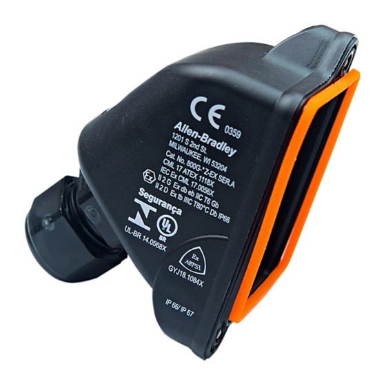
Bulletin 800G Latch Mount Back-of-Panel Modules
Catalog Numbers 800G-XLSx-EX; 800G-DLSx-EX; 800G-DLSxXx-EX; 800G-APMC; 800G-XLSxZ-EX; 800G-DLSxZ-EX; 800G-DLSxXxZ-EX
ATTENTION: To help prevent electrical shock, disconnect from
power source before installing or servicing. Follow NFPA 70E
requirements. Install in suitable enclosure. Keep free from
contaminants.
Only suitably trained personnel can install, adjust, commission,
use, assemble, disassemble, and maintain the product in
accordance with applicable code of practice. If a malfunction or
damage occurs, do not attempt to repair the product.
IMPORTANT
When working in hazardous areas, the safety of personnel
and equipment depends on compliance with the relevant
safety regulations. The people in charge of installation and
Maintenance bear a special responsibility. They must be
knowledgeable of the applicable rules and regulations.
These instructions provide a summary of the most important
installation measures. Everyone working with the product
must read these instructions so that they are familiar with the
correct handling of the product.
Keep these instructions for future reference as they must be
available throughout the expected life of the product.
Certifications
ATEX
IECEx
NEPSI
INMETRO
Gas Protection Type
Dust Type (with 800G-APMC cover only)
Ambient Temperature Range
Service Temperature Range
Mechanical and Electrical Ratings
Rated Insulation Voltage
Power Consumption
Rated Voltage (U
)
e
Illumination Colors (LED)
Contact Options
Utilization Category (AC)
Utilization Category (DC)
Conventional Thermal Current (I
)
the
Conductor Size
Degree of Protection
Contact Block (Screw Termination)
• Module: CML 17 ATEX 1107 U
• Module and cover: CML 17 ATEX 1118 X
• Module: IECEx CML 17.0047U
• Module and cover: IECEx CML 17.0056X
• Module: GYJ17.1398U
• Module and cover: GYJ18.1084X
• Module: UL-BR 14.0567U
• Module and cover: UL-BR 14.0568X
• Module: II 2 G Ex db eb IIC Gb
• Module and cover: II 2 G Ex db eb IIC T6 Gb
II 2 D Ex tb IIIC T80°C Db IP 66
-55...+40 °C (-67...+104 °F) @ 16 A
-55...+60 °C (-67...+140 °F) @ 11 A
-55...+85 °C (-67...+185 °F)
690V
—
AC 250V and 400V; DC 24V and 110V
—
1 N.O./1 N.C., 2 N.O., 2 N.C.
AC-12: 16 A, 400V; AC-15: 10 A, 400V
DC-13: 1 A, 24V; DC-13: 0.5 A, 110V
16 A/40 °C (104 °F)
11 A/60 °C (140 °F)
0.75 - 2.5 mm² (18...14 AWG)
IP20 (module only); IP64/IP66 (module and operator); IP66/IP67 (module, operator, and cover)
Product Description
• Contact block (catalog number 800G-XLSx-EX)
Contact blocks are used within hazardous areas where machine
functions are activated by pressing a button or actuating a
switch. These contact blocks are designed with self-cleaning
contacts and N.O. contacts feature positive break operation.
Contact blocks are compatible with all 800G non-illuminated
operators and the panel mount cover accessory (catalog
number 800G-APMC).
• Power module (catalog number 800G-DLSx-EX)
Power modules are used within hazardous areas to indicate the
functional status of respective machines visually by lighting up
or turning off. Power modules are compatible with all 800G
pilot light operators and the panel mount cover accessory
(catalog number 800G-APMC).
• Power module with contact block (catalog number
800GDLSxXx-EX)
Power module with contact block combination units are used
within hazardous areas where machine functions are activated
by depressing a push button and the corresponding functional
status is visually indicated. These units are compatible with all
800G illuminated push button operators and the panel mount
cover accessory (catalog number 800G-APMC).
Power Module (Screw Termination)
• Module: CML 17 ATEX 1108 U
• Module and cover: CML 17 ATEX 1118 X
• Module: IECEx CML 17.0048U
• Module and cover: IECEx CML 17.0056X
• Module: GYJ17.1399U
• Module and cover: GYJ18.1084X
• Module: UL-BR 14.0566U
• Module and cover: UL-BR 14.0568X
-55...+50 °C (-67...+122 °F) or 60 °C (140 °F) if U
300V
≤1 W
T
<50 °C (122 °F): 12...250V AC, 12...60V DC
a
T
<60 °C (140 °F): 12...24V AC/DC
a
Red, green, blue, white, or yellow
—
—
—
—
Power Module with Contact Block
(Screw Termination)
≤26.4V
e
1 N.O., 1 N.C.
AC-15: 1 A, 230V
DC-13: 0.25 A, 24V
—
Advertisement
Table of Contents

Related Manuals for Rockwell Automation Allen-Bradley 800G-XLS Z-EX Series


Summary of Contents for Rockwell Automation Allen-Bradley 800G-XLS Z-EX Series
-
Page 1: Product Description
Installation Instructions Original Instructions Bulletin 800G Latch Mount Back-of-Panel Modules Catalog Numbers 800G-XLSx-EX; 800G-DLSx-EX; 800G-DLSxXx-EX; 800G-APMC; 800G-XLSxZ-EX; 800G-DLSxZ-EX; 800G-DLSxXxZ-EX Product Description ATTENTION: To help prevent electrical shock, disconnect from power source before installing or servicing. Follow NFPA 70E • Contact block (catalog number 800G-XLSx-EX) requirements. -
Page 2: Safety Instructions
4. Turn the locking bolt to secure the contact block or power product by anyone other than the manufacturer is not permitted and module to the front-of-panel operator. exempts Rockwell Automation from liability for defects and any further liability. Installation — Modules... - Page 3 Accessories and Replacement Parts 9. Tighten the screws (5) with a torque of For more accessories and replacement parts that Rockwell Automation 0.5…0.6 N·m (4.4…5.3 lb·in). offers, see https://ab.rockwellautomation.com/Push-Buttons/ Hazardous-Location/800G.
-
Page 4: Declaration Of Conformity
Rockwell Otomasyon Ticaret A.Ş., Kar Plaza İş Merkezi E Blok Kat:6 34752 İçerenköy, İstanbul, Tel: +90 (216) 5698400 Publication 800G-IN003B-EN-P - May 2018 10001129318 Ver 02 Supersedes Publication 800G-IN003A-EN-P - April 2015 Copyright © 2018 Rockwell Automation, Inc. All rights reserved. Printed in the U.S.A.
Need help?
Do you have a question about the Allen-Bradley 800G-XLS Z-EX Series and is the answer not in the manual?
Questions and answers