Table of Contents
Advertisement
Quick Links
Response
SELV
CONTINUOUS EXTRACT FAN
Installation and Wiring Instructions
FAN UNIT 12V DC SELV (CLASS III)
CONTROLLER 220-240V 50Hz MAINS SUPPLY (CLASS II)
WITH 12V DC SELV OUTPUT
PLEASE READ INSTRUCTIONS IN CONJUNCTION WITH ILLUSTRATIONS.
PLEASE SAVE THESE INSTRUCTIONS.
Stock Ref. N°
Response
SELV TP
404878
Response
SELV HTP
404879
IPX7
Advertisement
Table of Contents

Related Manuals for Vent-Axia Response SELV TP


Summary of Contents for Vent-Axia Response SELV TP
- Page 1 Response SELV CONTINUOUS EXTRACT FAN Installation and Wiring Instructions Stock Ref. N° Response SELV TP 404878 Response SELV HTP 404879 FAN UNIT 12V DC SELV (CLASS III) CONTROLLER 220-240V 50Hz MAINS SUPPLY (CLASS II) WITH 12V DC SELV OUTPUT IPX7 PLEASE READ INSTRUCTIONS IN CONJUNCTION WITH ILLUSTRATIONS.
-
Page 2: Safety And Guidance Notes
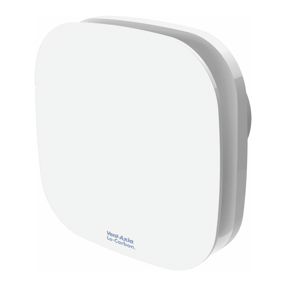
D. The Fan should only be used in conjunction with the appropriate Vent-Axia products. E. The fan should only be used in conjunction with fixed wiring. F. When the Fan is used to remove air from a room containing a fuel-burning appliance, ensure that the air replacement is adequate for both the fan and the fuel-burning appliance. - Page 3 J. Young children should be supervised to ensure that they do not play with the appliance. DESCRIPTION The Response SELV fan is a continuously running extract fan for kitchens, utility rooms, bathrooms and toilets. The electrical supply to this fan is 12V DC SELV from the mains controller.
-
Page 4: Wall Mounting
WALL MOUNTING For wall mounting cut a 117mm diameter hole through the wall and insert the wall sleeve. Slope the sleeve slightly downwards away from the fan. Where necessary cut to length and cement both ends into position flush with the wall faces. Fix exterior grille into position with the louvres positioned downwards. - Page 5 • Push dip switch 1 (SW1) into the off position to turn off constant flow mode. (Factory set) IMPORTANT – On first power up, the fan will run through its initialisation routine. For the first 15 minutes, the flow rate, pressure and day logger will be displayed. The fan may not be fully functional until this is over.
-
Page 6: Servicing And Maintenance
To remove the pullcord, cut the cord and leave the switch in place. There is no need to switch the fan on/off beforehand. 8) System pressure detection (TP & HTP models) The fan can detect the system pressure for fault finding. If the fan seems noisy or cannot achieve the desired flow rate, this could be due to a blocked duct or the ducting has not been suitably stretched during installation (if flexible ducting is used). -
Page 7: Troubleshooting
1. At intervals appropriate to the installation, the fan should be inspected and cleaned to ensure there is no build-up of dirt or other deposits. 2. Carefully pull the front panel off the inner grille. (fig. 4) 3. Wipe the inlets and front face with a damp cloth until clean. Be careful not to push dirt into the airflow sensor. - Page 8 Siting fan. Fig.1 Continuous trickle (6l/s or 8l/s) with pullcord boost (13l/s) 1 Phase Supply (220-240V 50Hz). FUSE 12V D.C SELV Supply Switched Fused Spur (3A) Controller Fig.2 Continuous boost (13l/s) 12V D.C 1 Phase Supply SELV Supply (220-240V 50Hz). FUSE LINK Switched...
- Page 9 Fig.4. Removing the grille for wiring and setting the controls Pull front panel as shown. Loosen screws – DO NOT REMOVE FROM GRILLE (the screws are self-retaining) Pull inner grille away from housing as shown. When replacing grille, ensure the flow sensor is aligned with the corresponding slot in the grille.
- Page 10 Fig. 6. Display and prism The display can only be seen from the side. This is to allow the installer to view the display with the cover attached as this can affect the airflow through the sensor. Every 10-20 seconds the display will switch between displaying airflow rate and system pressure. The system pressure will flash.
- Page 11 Vent-Axia guarantees its products for two years from date of purchase against faulty material or workmanship. In the event of any part being found to be defective, the product will be repaired, or at the Company’s option replaced, without charge, provided that the product:- Has been installed and used in accordance with the instructions given with each unit.
- Page 12 SALES ENQUIRIES: Tel: 0344 8560590 Fax: 01293 565169 TECHNICAL SUPPORT: Tel: 0344 8560594 Fax: 01293 539209 For details of the warranty and returns procedure please refer to www.vent-axia.com or write to Vent-Axia Ltd, Fleming Way, Crawley, RH10 9YX 404896 H 0617...
Need help?
Do you have a question about the Response SELV TP and is the answer not in the manual?
Questions and answers