Advertisement
Quick Links
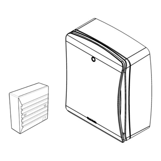
Lo-Carbon
SOLO Plus
SELV
Centrifugal
Bathroom/Toilet Fan
Installation and Wiring Instructions
FAN UNITS 12V DC SELV (CLASS III)
CONTROLLERS 220-240V 50Hz MAINS SUPPLY (CLASS II)
WITH 12V DC SELV OUTPUT
PLEASE READ INSTRUCTIONS IN CONJUNCTION WITH THE ILLUSTRATIONS.
PLEASE SAVE THESE INSTRUCTIONS
Stock Ref. N°
427485B (P)
427486B (T)
427487B (HT)
427488B (TM)
T
IPX7
(FAN)
Advertisement

Subscribe to Our Youtube Channel
Related Manuals for Vent-Axia SOLO Plus SELV


Summary of Contents for Vent-Axia SOLO Plus SELV
- Page 1 Lo-Carbon SOLO Plus SELV Centrifugal Bathroom/Toilet Fan Installation and Wiring Instructions Stock Ref. N° 427485B (P) 427486B (T) 427487B (HT) 427488B (TM) FAN UNITS 12V DC SELV (CLASS III) CONTROLLERS 220-240V 50Hz MAINS SUPPLY (CLASS II) WITH 12V DC SELV OUTPUT PLEASE READ INSTRUCTIONS IN CONJUNCTION WITH THE ILLUSTRATIONS.
-
Page 2: Safety And Guidance Notes
Installation and Wiring Instructions for the Lo-Carbon SOLO Plus SELV Bathroom Extract Fan. IMPORTANT: READ THESE INSTRUCTIONS BEFORE COMMENCING THE INSTALLATION DO NOT install this product in areas where the following may be present or occur: • Excessive oil or a grease laden atmosphere. -
Page 3: Panel Mounting (Flush)
CONTROLLER. DESCRIPTION As standard, the Lo-carbon SOLO Plus SELV is suitable for panel/wall installations, flush or surface mounting, either in a horizontal or vertical plane. 100mm ducting (flexible or straight) can be attached using the supplied adjustable spigot, providing rear or side exit options. Adaptors for System 25 and System 50 ducting can be used in conjunction with the adjustable spigot. - Page 4 2. Removing the grille. Firstly remove the front cover by carefully pulling each corner of the front panel until it is free to be removed from the inner grille (Fig 1). Unscrew the two screws at the bottom of the inner grille. The screws will remain in the inner grille but will be loose when the grille is ready to be removed (Fig 1).
-
Page 5: Servicing And Maintenance
1. SELECTING THE CONSTANT TRICKLE OPTION - Switch dip switch 2 into the ON position to activate the constant trickle operation. To disable the constant trickle option, move dip switch 2 into the OFF position. (Fig 7). 2. SELECTING THE TRICKLE SPEED (if enabled) This will determine the speed at which the fan will run continuously if the constant trickle speed option is enabled (1 above). - Page 6 Fig. 1. Removing the grille Fig. 2. Fig. 3. Surface mounting screw hole locations Attaching the spigot Fig. 4. Converting outlet spigot for side exit and recess mounting...
- Page 7 Fig. 5. Fig. 6. PIR sensor cable - ( TM only Recess mounting clips In 3 positions. To remove the cover on TM models the sensor lead must be disconnected Fig. 7. Settings Top view of PCB cover showing pot locations And dip switch location LED position Timer adjuster...
- Page 8 Fig. 8. P/TM wiring diagram Fig. 9. T/HT wiring diagram...
-
Page 9: Product Fiche
PRODUCT FICHE For Residential Ventilation Units (Complying Commission Delegated Regulation (EU) No 1254/2014) Name: Vent-Axia Vent-Axia Vent-Axia Vent-Axia Lo-Carbon Solo Plus Lo-Carbon Solo Plus Lo-Carbon Solo Plus Lo-Carbon Solo Plus Model ID (Stock Ref.) : SELV P - 427485 SELV T - 427486... - Page 10 Notes:-...
- Page 11 Notes:-...
- Page 12 Vent-Axia guarantees its products for two years from date of purchase against faulty material or workmanship. In the event of any part being found to be defective, the product will be repaired, or at the Company’s option replaced, without charge, provided that the product:- •...
Need help?
Do you have a question about the SOLO Plus SELV and is the answer not in the manual?
Questions and answers