Table of Contents
Advertisement
Advertisement
Table of Contents

Subscribe to Our Youtube Channel
Related Manuals for Leuze electronic RSL 410


Summary of Contents for Leuze electronic RSL 410
- Page 1 EN 2015/11 - 50128230 We reserve the right to make technical changes...
- Page 2 © 2015 Leuze electronic GmbH + Co. KG In der Braike 1 D-73277 Owen / Germany Phone: +49 7021 573-0 Fax: +49 7021 573-199 http://www.leuze.com info@leuze.de Leuze electronic RSL 410...
-
Page 3: Table Of Contents
Speed-dependent protective function for vehicles....... 32 Leuze electronic RSL 410... - Page 4 Saving configuration ........... . . 69 Leuze electronic RSL 410...
- Page 5 EC Declaration of Conformity........108 Leuze electronic RSL 410...
-
Page 6: About This Document
Indicates dangers that may result in severe or fatal injury if the measures for danger avoidance are not followed. DANGER Signal word for life-threatening danger Indicates dangers with which serious or fatal injury is imminent if the measures for danger avoidance are not followed. Leuze electronic RSL 410... -
Page 7: Checklists
The checklists contain minimum testing requirements. Depending on the application, other tests may be necessary. Leuze electronic RSL 410... -
Page 8: Safety
• The safety sensor must be inspected regularly by a competent person to ensure proper integration and mounting (see chapter 2.4). • The safety sensor must be exchanged after a maximum of 20 years. Repairs or exchange of wear parts do not lengthen the mission time. Leuze electronic RSL 410... -
Page 9: Vapors, Smoke, Dust, Particles
The protection of personnel and the device cannot be guaranteed if the device is operated in a manner not complying with its intended use. Leuze electronic GmbH + Co. KG is not liable for damages caused by improper use. Read these original operating instructions before commissioning the device. -
Page 10: Responsibility For Safety
Manipulating the safety sensor also voids all warranty claims against the manufacturer of the safety sensor. Repairs must only be performed by Leuze electronic GmbH + Co. KG. Responsibility for safety Manufacturer and operating company must ensure that the machine and implemented safety sensor func- tion properly and that all affected persons are adequately informed and trained. -
Page 11: Exemption Of Liability
Safety Exemption of liability Leuze electronic GmbH + Co. KG is not liable in the following cases: • The safety sensor is not used as intended. • Safety notices are not adhered to. • Reasonably foreseeable misuse is not taken into account. -
Page 12: Device Description
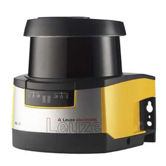
SILCL in accordance with IEC/EN 62061 Performance Level (PL) in accordance with EN ISO 13849-1 Scanner unit Connection unit Optics cover Alphanumerical display (displayed) LED indicators Figure 3.1: Device overview of safety laser scanner RSL 400 Leuze electronic RSL 410... -
Page 13: Device Overview
Device description All safety sensors of the RSL 410 series are equipped as follows: • Laser scanner with the range class S, M, L or XL: Range class Operating range [m] 3.00 6.25 8.25 • 24-digit alphanumerical display • Integrated electronic spirit level for aligning the safety sensor •... -
Page 14: Parameters For Protective Function
• Attachment point for mounting, either directly or using an optional mounting system When devices are swapped out, the connection unit remains mounted and aligned. • EMC wiring for signal inputs/outputs and supply using M12 plug Safety sensor Connection unit Connection RSL 410 CU408-M12 M12 plug, 8-pin Leuze electronic RSL 410... -
Page 15: Display Elements
Protective field occupied RES activated and blocked but ready to be unlocked Protective field free and linked sensor enabled (if applicable) Blue No internal function call active (e.g. warning field free) Internal function call (e.g. warning field occupied) Leuze electronic RSL 410... -
Page 16: Alphanumerical Display
H +/- ..° V +/- .. ° Horizontal alignment in degrees: H H -3° V +9° Vertical alignment in degrees: V Sensor detection Device PING received Display for identification by device name PING received name Message Leuze electronic RSL 410... -
Page 17: Field-Of-View Display
(see table 17.3). Loop guard (optional) The loop guard for the optics cover prevents damage to the safety sensor caused by light contact with foreign objects. The loop guard is available as an accessory (see table 17.3). Leuze electronic RSL 410... -
Page 18: Configuration And Diagnostic Software Sensor Studio
• Each device DTM has a communication DTM that sets up and monitors the communication connec- tions to the sensor. Only use the software for safety sensors manufactured by Leuze electronic. System requirements To use the software, you need a PC or laptop with the following specifications:... - Page 19 RSL 400 device DTM. The password for the safety sensor only needs to be entered (i.e. the access level only needs to be changed) when the changes are downloaded to the safety sensor (see chapter 4.5.1). Leuze electronic RSL 410...
-
Page 20: User Interface
The device managers (DTM) of the safety sensors are created and managed in the FDT frame menu. Device manager DTM Configuration projects for setting up the selected safety sensor are created and managed in the device managers (DTM) of the safety sensors. Leuze electronic RSL 410... -
Page 21: Fdt Frame Menu
DTM to communication DTM. Start the DTM change function in the FDT frame menu by clicking the button. DTM change Information on can be found in the online help for the FDT frame menu under Sensor Studio Options. Leuze electronic RSL 410... -
Page 22: User Management
Start the configuration and diagnostics software on the PC by double-clicking the button. • The mode selection of the Project Wizard is displayed. • If the mode selection is not shown, start the Project Wizard in the FDT frame menu by clicking the [Project Wizard] button ( Leuze electronic RSL 410... - Page 23 Select the interface and click the [Start] button. Find the safety sensor for your configuration project using the search function of the communication DTM. FDT frame menu Communication DTM Device list Search function Figure 4.4: Communication DTM with search function Leuze electronic RSL 410...
- Page 24 The device manager (DTM) starts without querying the access level of the user. During commu- nication with the safety sensor, the safety sensor does however query the access level of the user. To change the access levels (see chapter 4.5.1 "Selecting access level"). Leuze electronic RSL 410...
-
Page 25: Selecting Access Level
• Inputs / outputs 4.5.4 CONFIGURATION see chapter 9 "Configuring the safety sensor" You can only transfer changes made in the CONFIGURATION menu to the safety sensor if you Engineer are logged in with the access level Leuze electronic RSL 410... -
Page 26: Diagnosis
Create and save service file The service file contains all available information on the safety sensor as well as configuration and settings. When requesting support, send the service file to the Leuze electronic customer service (see chapter 14 "Service and support"). Sensor display Device display in the DTM menu •... - Page 27 Generate a one-time password. Note down the generated one-time password. Send the one-time password to the Leuze electronic customer service for confirmation (see chapter 14 "Service and support"). The device can now be switched off and the connection can be terminated.
-
Page 28: Functions
• Changing the safety configuration as well as the communication and diagnostics settings of the sen- sor is only permitted for certain access levels. • Installation and operation of the software do not depend on the access level of the user. The following access levels are available: Leuze electronic RSL 410... -
Page 29: Function Modes Of Safety Sensor
You use the protective function to define the criteria for switching off the safety-related switching outputs (see chapter 3.1.2 "Parameters for protective function"). The changeover-capable protective and warning field pairs for the selected function mode are defined in the configuration banks, e.g. CONFIGURATION > Protective function A > Bank A1. Leuze electronic RSL 410... -
Page 30: One Protective Function
The signals are assigned to the switching outputs via the configuration and diagnostics software (CONFIGURATION > Outputs; see chapter 9 "Configuring the safety sensor"). Table 5.3: Example: Assignment of signals to switching outputs Leuze electronic RSL 410... - Page 31 Switching output MELD – not safe Protective function B: Violation of protec- tive field A-WF-VIO Switching output A1 Protective function A: Violation of warn- ing field B-WF-VIO Switching output EA1 Protective function B: Violation of warn- ing field Leuze electronic RSL 410...
-
Page 32: Selectable Resolution For Hand, Leg And Body Detection
• The function is taken over by a downstream safety-related component of the machine control system. • It is not possible to walk behind or go around the effective protective field. Leuze electronic RSL 410... -
Page 33: Start Interlock/Automatic Restart
ISO 12100. Using start/restart interlock In addition to the safety sensor you must also install the reset button. The machine operator starts the machine with this reset button. Leuze electronic RSL 410... -
Page 34: Reference Contour Monitoring
A message is displayed on the alphanumerical display and the safety sensor switches to the fault interlock state: • With the OSSDs switched off, +24 V must be present at the EDM input. • With the OSSDs switched on, the EDM circuit must be open (high impedance). Leuze electronic RSL 410... -
Page 35: Applications
In accordance with EN ISO 13855, resolutions from 14 to 40 mm make sense here. This yields the necessary safety distance for finger protection, among others (see chapter 7.3 "Stationary point of operation guarding"). Leuze electronic RSL 410... -
Page 36: Stationary Access Guarding
(DTS). The distance between the protective field front edge and the vehicle front must be greater than the stopping distance of the vehicle with selected speed and maximum load. A safe control system selects speed-dependent protective fields and can activate side horizontal protective fields for curved stretches. Leuze electronic RSL 410... - Page 37 Protective field 1 for forward travel, deactivated Protective field 2 for forward travel, activated Protective field 1 for reverse travel, activated Protective field 2 for reverse travel, deactivated Warning field for reverse travel Figure 6.3: Mobile danger zone guarding Leuze electronic RSL 410...
-
Page 38: Danger Zone Guarding On Side-Tracking Skates
The safety sensors are positioned laterally and the protective fields are arranged vertically, at a slight tilt. The position of the front edges of the side protective fields is oriented here on the position of the front edge of the horizontal protective field. Leuze electronic RSL 410... - Page 39 Protective and warning field pair for side guarding, left, activated Protective and warning field pair for side guarding, right, activated Protective and warning field pair for reverse travel, deactivated Figure 6.5: Mobile side guarding on side-tracking skates Leuze electronic RSL 410...
-
Page 40: Mounting
= Response time of the safety relay = Machine stopping time [mm] = Additional distance to the safety distance If longer stopping times are determined during regular inspections, an appropriate additional time must be added to t Leuze electronic RSL 410... -
Page 41: Suitable Mounting Locations
• Make sure that the scanning range of the safety sensor is not limited. To mount the safety sensor taking the scanning range into consideration, a template must be attached to the top cover of the safety sensor. Leuze electronic RSL 410... - Page 42 Have the appropriate tools at the ready and mount the safety sensor. Install protective enclosures or safety bars if the safety sensor is in an exposed position. Leuze electronic RSL 410...
- Page 43 You can easily test the safety sensor along this marking. After mounting, you can electrically connect (see chapter 8 "Electrical connection"), start up, align (see chapter 10 "Starting up the device"), and check (see chapter 11 "Testing") the safety sensor. Leuze electronic RSL 410...
-
Page 44: Mounting Examples
Mounting examples 54,6 all dimensions in mm Safety sensor Post Mounting bracket BT856M Figure 7.3: Example: mounting on a post all dimensions in mm Safety sensor Mounting bracket BT840M Figure 7.4: Example: mounting on a chamfered corner Leuze electronic RSL 410... -
Page 45: Information On Protective Field Dimensioning
There is an area behind the safety sensor that the safety sensor does not monitor. Unmonitored areas can also materialize, e.g. if you install a safety sensor on a rounded off vehicle front. It must not be possible to walk behind unmonitored areas. Leuze electronic RSL 410... - Page 46 Stepping behind protection by countersinking into the machine contour Use a physical cover set at an angle over the safety sensor if you expect that the safety sensor will be used as a climbing aid or standing surface. Leuze electronic RSL 410...
- Page 47 Shielding prevents reciprocal influencing of safety sensors set up beside one another Install the safety sensors off-set on the height. Minimum distance, min. 100 mm Scan level Figure 7.9: Height offset mounting, parallel alignment Install the safety sensors with crossed alignment. Leuze electronic RSL 410...
-
Page 48: Stationary Danger Zone Guarding
120 ms or higher. Determine the machine/system's stopping time t If data is not available, you can commission Leuze electronic to perform measurements; see chapter 14 "Service and support". If an increase in the stopping time within the regular test periods is to be expected, take an additional... - Page 49 Figure 7.12: Defining the protective field contour for a stationary, horizontal protective field Define the limits of the protective field using the safety distance S without an additional distance. Determine the biggest protective field radius R for this protective field. Leuze electronic RSL 410...
-
Page 50: Stationary Point Of Operation Guarding
Prevent obstructions within the calculated protective field boundaries. If this is not possible, implement protective measures so that the point of operation cannot be reached from out of the shadow of the obstruction. Stationary point of operation guarding The safety sensor takes over the stop-activating and presence-detecting function. Leuze electronic RSL 410... - Page 51 80 ms or higher. Determine the machine/system's stopping time t If data is not available, you can commission Leuze electronic to perform measurements (see chapter 14 "Service and support"). If an increase in the stopping time within the regular test periods is to be expected, take an additional...
-
Page 52: Stationary Access Guarding
1600 mm/s. Determine the machine/system's stopping time t If data is not available, you can commission Leuze electronic to perform measurements (see chapter 14 "Service and support"). Leuze electronic... -
Page 53: Mobile Danger Zone Guarding On Dtss
The beam level of the safety sensor is level with the alphanumerical display. 7.5.1 Minimum distance D [mm] = Minimum distance, vehicle front (danger) to protective field front edge [mm] = Stopping distance [mm] = Total required additional distances Leuze electronic RSL 410... - Page 54 You determine the addi- tional distance Z according to the following diagram: 20 40 60 80 100 120 140 160 Figure 7.15: Diagram for determining the additional distance Z with lack of floor space H Leuze electronic RSL 410...
-
Page 55: Protective Field Dimensions
For mobile vertical protective fields use a resolution of at least 150 mm. Position the protective field edges in the travel direction in accordance with the front protective field edge of the horizontal protective field. Leuze electronic RSL 410... -
Page 56: Mounting Accessories
Mount the mounting system on the wall mount or on the mounting bracket for floor mounting. Attach the safety sensor to the mounting system. Tightening the screws fixes the safety sensor in position. Align the safety sensor using the integrated electronic spirit level. Leuze electronic RSL 410... -
Page 57: Loop Guard
Mounting bracket for floor mounting BTF815M (only with mounting system BTU800M) Mounting system BTU800M Loop guard Safety sensor Figure 7.18: Loop guard Attach the safety sensor to the mounting system. Engage the loop guard for the optics cover from above into the mounting system. Leuze electronic RSL 410... -
Page 58: Electrical Connection
Ethernet connection. Interfaces The safety sensor has two interfaces: • Interface for connection with the control system • Interface for communication with PC or laptop Leuze electronic RSL 410... -
Page 59: Pin Assignment For Control M12
The shield of the connection cable is on the thread of the M12 plug. The thread is part of the metallic housing. 8.2.2 Pin assignment of M12 Ethernet interface (communication) ( D-coded) The safety sensor is equipped with a 4-pin M12 connector. Leuze electronic RSL 410... -
Page 60: Connection Unit Cu408-M12
Connection unit CU408-M12 M5 2x M12 socket, A-coded, connection to the control M12 socket, D-coded, Ethernet communication connection Connection for functional earth with M5 x 10 self-cutting/self-tapping (gas tightness) and ground strap Figure 8.3: Connection unit CU408-M12 Leuze electronic RSL 410... -
Page 61: Circuit Diagram Example
Electrical connection Circuit diagram example Spark extinction circuit, suitable spark extinction provided Figure 8.4: RSL 410 with MSI-SR4B safety relay Leuze electronic RSL 410... -
Page 62: Configuring The Safety Sensor
If the monitoring time is increased to above 5 s or if manipulation protection is deactivated, the system operator must introduce other measures to prevent manipulation. For example, make sure that the distance range in which manipulation is possible cannot be accessed by personnel under normal operating conditions. Leuze electronic RSL 410... - Page 63 The configuration data is stored in the connection unit of the safety sensor and is therefore also available after replacement or repair of the scanner unit. The configuration data only needs to be transferred again if changes are made to the configuration. Leuze electronic RSL 410...
-
Page 64: Connecting Safety Sensor To Pc
Assign permanent IP address Select the menu command Communication > LAN. In the DHCP dialog box, deactivate the Obtain IP address automatically checkbox. In the CONNECTION SETTINGS dialog box, enter the IP address information. Leuze electronic RSL 410... -
Page 65: Determining Configuration Project
Alternatively, you can select the safety sensor by entering the part number or by specifying the sensor range and the sensor type. The device manager (DTM) of the safety sensor shows the initial screen for the configuration project. Leuze electronic RSL 410... -
Page 66: Configuring Protective Function
[]By clicking Next, you can proceed to the next configuration step without selecting the corresponding option in the CONFIGURATION menu. If you make changes to the default settings in a configuration step, first click the [Confirm] button and then [Next]. Administration OSSDs Protective function A Leuze electronic RSL 410... -
Page 67: Entering Administration Parameters
The RESOLUTION, RESPONSE TIME and START-UP BEHAVIOR dialog boxes are displayed. In the RESOLUTION dialog box, enter the resolution and, if applicable, the maximum speed of a driv- erless transportation system (DTS) in the input fields. Leuze electronic RSL 410... - Page 68 Field editor with toolbar for field definition In the CONFIGURATION menu, click the field pair the protective and warning fields of which you want to define. Click the button and define the contours and boundaries of the protective field. Leuze electronic RSL 410...
-
Page 69: Saving Configuration
• If no individual password has been defined for the access level , use the preset default password (safety). Alternatively, you can transfer a configuration project saved as a file on the PC directly to the safety sensor. Leuze electronic RSL 410... - Page 70 Confirm successful transfer of the safety configuration to the safety sensor with [OK]. The safety configuration has only been successfully transferred to the safety sensor when the confirma- tion dialog is displayed during the download. Leuze electronic RSL 410...
-
Page 71: Selecting Access Level
In the DTM menu bar, click the [Reset safety configuration] button. Engineer Users with the access level can additionally transfer the changed safety configuration to the safety sensor (see chapter 9.6 "Transferring configuration project to safety sensor"). Leuze electronic RSL 410... -
Page 72: Starting Up The Device
Temporarily shutting down the machine with the safety sensor When you shut down the machine with the safety sensor temporarily, you do not have to observe any more steps. The safety sensor saves the configuration and starts again with the switch-on with this configuration. Leuze electronic RSL 410... -
Page 73: Restarting
If the range and/or performance class of the replacement scanner unit is not compatible with the original scanner unit, you must adapt the configuration of the safety sensor to the replacement scanner unit. Connect the safety sensor's Ethernet communication interface with the PC. Leuze electronic RSL 410... - Page 74 If you transferred a new configuration to the safety sensor, check the safety sensor according to the rou- tine for initial start-up (see chapter 11.1.1 "Checklist for integrator – to be performed prior to the initial start-up and following modifications"). Leuze electronic RSL 410...
-
Page 75: Testing
(see chapter 15 "Technical data")? Is the safety sensor correctly aligned and are all fastening screws and connec- tors secure? Are safety sensor, connection cables, connectors, protection caps and command devices undamaged and without any sign of manipulation? Leuze electronic RSL 410... - Page 76 Are settings that could result in an unsafe state possible only by means of key, password or tool? Are there incentives that pose stimulus for tampering? Were the operators instructed prior to starting work? a) not applicable Leuze electronic RSL 410...
-
Page 77: To Be Performed Periodically By Competent Persons
11.3.1 Checklist – periodically by the operator NOTICE If you answer one of the items on the check list with , the machine must no longer be operated (see table 11.1). Leuze electronic RSL 410... - Page 78 – are the obviously dangerous machine parts stopped without noticeable delay? Protective device with presence detection: the protective field is interrupted with the test object – does this prevent operation of the obviously dangerous machine parts? Leuze electronic RSL 410...
-
Page 79: Diagnostics And Troubleshooting
Analyze the cause of the fault using the diagnostics displays and rectify the fault. If you are unable to rectify the fault, contact the Leuze electronic branch responsible for you or call the Leuze electronic customer service (see chapter 14 "Service and support"). - Page 80 Swap out the safety sensor or change the unknown field pair selection parameter. configuration. The type of safety sensor must be the same as the type stored in the Sensor Studio connection unit or in the soft- ware. Leuze electronic RSL 410...
- Page 81 Check the wiring of the downstream relays and that they are functioning correctly. U0574 Switching fault, EDM at OSSD A: external Check the wiring of the downstream relays relay does not switch off. and that they are functioning correctly. Leuze electronic RSL 410...
- Page 82 U0661 Safety-related switching outputs (OSSDs) Check the wiring of the OSSDs. cannot be switched: short circuit with 0 V, +24 V DC or between OSSDs. Leuze electronic RSL 410...
- Page 83 F..The monitoring functions have detected an Create the service file (see chapter 4.5.5 internal error. "DIAGNOSIS")and contact the Leuze electronic customer service (see chapter 14 "Service and support"). Leuze electronic RSL 410...
-
Page 84: Care, Maintenance And Disposal
Check the safety sensor according to the routine for initial start-up (see chapter 11.1.1 "Checklist for integrator – to be performed prior to the initial start-up and following modifications"). Leuze electronic RSL 410... -
Page 85: Cleaning The Optics Cover
The device does not normally require any maintenance by the operator. Repairs to the device must only be performed by the manufacturer. For repairs, contact your responsible Leuze electronic subsidiary or Leuze electronic customer service (see chapter 14 "Service and support"). -
Page 86: Service And Support
Monday to Thursday, from 8.00 a.m. to 5.00 p.m. (UTC+1) Friday, 8.00 a.m. to 4.00 p.m. (UTC+1) E-mail: service.protect@leuze.de Return address for repairs: Service center Leuze electronic GmbH + Co. KG In der Braike 1 D-73277 Owen / Germany Leuze electronic RSL 410... -
Page 87: Technical Data
Angular resolution 0.1 ° Tolerance field of reference contour + 200 mm Table 15.3: Protective field data Safety sensor RSL 410 RSL 420 RSL 430 RSL 440 Number of field pairs 10 + 10 Reference contour selectable Minimum adjustable range... - Page 88 Approx. 700 mA (use power supply unit with 3 A) Power consumption 17 W with 24 V plus output capability Overvoltage protection Overvoltage protection with protected limit stop Protective conductor Connection required Device connection Connection cable, M12-8 connector Connection socket for Ethernet/communication M12-4 connector, D-coded Leuze electronic RSL 410...
- Page 89 (-10 mA) power contactor (EDM) AX=output 100 mA Lamp (PNP only) Current limited, short-circuit proof (-20 mA) Control input (PNP/ (A1, MELD) NPN) Signal definition: High/logical 1 16 - 30 V Low/logical 0 < 3 V Leuze electronic RSL 410...
- Page 90 140 x 149 x 140 (W x H x D) in mm plug with fixing and connection cable) Weight of standard version incl. connection unit Approx. 3 kg Distance, beam level center to bottom housing edge 104 mm Leuze electronic RSL 410...
-
Page 91: Dimensions
Technical data 15.2 Dimensions M5 2x 61,3 140,2 140,3 all dimensions in mm Scan level Figure 15.1: Dimensions safety laser scanner with connection unit Leuze electronic RSL 410... - Page 92 Mounting dimensions safety laser scanner with connection unit all dimensions in mm Figure 15.3: Minimum space requirements for installation and replacement of scanner unit all dimensions in mm Reference point for distance measurement and protective field radius Figure 15.4: Dimensions of scanning range Leuze electronic RSL 410...
-
Page 93: Dimensioned Drawings: Accessories
Technical data 15.3 Dimensioned drawings: Accessories 157,5 166,3 all dimensions in mm Figure 15.5: Mounting system BTU800M Leuze electronic RSL 410... - Page 94 Technical data all dimensions in mm Figure 15.6: Mounting bracket BTF815M Leuze electronic RSL 410...
- Page 95 Technical data all dimensions in mm Figure 15.7: Mounting bracket BTF830M Leuze electronic RSL 410...
- Page 96 Technical data all dimensions in mm Figure 15.8: Loop guard BTP800M 205,2 all dimensions in mm Figure 15.9: Mounting bracket BT840M Leuze electronic RSL 410...
- Page 97 Technical data all dimensions in mm Figure 15.10: Mounting bracket BT840M, view A 233,5 all dimensions in mm Figure 15.11: Mounting bracket BT856M Leuze electronic RSL 410...
- Page 98 Technical data all dimensions in mm Figure 15.12: Mounting bracket BT856M, view A Leuze electronic RSL 410...
- Page 99 Technical data 120,4 all dimensions in mm Figure 15.13: Drilling template for adapter plate, RS4/ROD4 BT800MA Leuze electronic RSL 410...
-
Page 100: Representation Of Safety Sensor Status
Representation of status Byte Signal Description Value 0 Value T Default Type (variant) of status profile. Extensions require new type of status profile OP-MODE Operating mode: • 1: Safety mode • 2: Simulation mode Messages and OSSDs Leuze electronic RSL 410... - Page 101 Mode-PARK Park request fulfilled Parked RFL-SEG-1 Reflector area 1 Reflector detected RFL-SEG-2 Reflector area 2 Reflector detected RFL-SEG-3 Reflector area 3 Reflector detected RFL-SEG-4 Reflector area 4 Reflector detected reserved reserved Electrical signals at sensor connection Leuze electronic RSL 410...
- Page 102 RES1 Start input Protective function A RES2 Start input Protective function B EDM input Protective function A EDM input Protective function B Linkage input Linkage input PNP-NPN PNP/NPN changeover Output Output Output Output MELD Output reserved Leuze electronic RSL 410...
- Page 103 A-PAIR-SEL 1 First selected field pair A Numbers 1 … 10 A-PAIR-SEL 2 Second selected field pair A Numbers 1 … 10 A-PAIR-SEL 3 Third selected field pair A Numbers 1 … 10 Output signals A Leuze electronic RSL 410...
- Page 104 Protective function A A-PF-VIO-SEG-2 Status of active protective field Violation Free segment Protective function A A-FP-SEL-1 Defined field pair selected Selected Protective function A A-FP-SEL-2 Defined field pair selected Selected Protective function A reserved reserved Leuze electronic RSL 410...
-
Page 105: Standards And Legal Regulations
• EN IEC 62061 [12] • EN IEC 60204 [18] • EN ISO 13849-1:200 [13] • EN ISO 13855:2010 [14] • EN/IEC 61496-3 [15] • EN 1525 [16] • EN 999 [21] • IEC/TS 62046:2008 [17] Leuze electronic RSL 410... -
Page 106: Ordering Information And Accessories
1 OSSD pair; 1 field pair; 3 IOs; extra long range Connection units 53800117 CU408-M12 Connection: M12, 8-pin Ethernet: M12, 4-pin 53800125 CU411-RS4 RS4 adapter Connection: cable, 11-wire, SUB-D 15, length: 6 m Ethernet: M12, 4-pin Leuze electronic RSL 410... - Page 107 Drilling template for adapter plate, RS4/ROD4 Cleaning fluids 430400 Cleaning set 1 Cleaning fluid for plastic, 150 ml, cleaning cloths, 25x, soft, fuzz-free 430410 Cleaning set 2 Cleaning fluid for plastic, 1,000 ml, cleaning cloths, 100x, soft, fuzz-free Leuze electronic RSL 410...
-
Page 108: Ec Declaration Of Conformity
Liebigstr. 4; 82256 Fuerstenfeldbruck; Germany Datum / Date / Date Ulrich Balbach, Geschäftsführer / Director / Directeur Leuze electronic GmbH + Co. KG, Sitz Owen|Registergericht Stuttgart, HRA 230712 Liebigstraße 4, D-82256 Fürstenfeldbruck|T +49 8141 5350-0, F +49 8141 5350-190|info@leuze.de, www.leuze.de Persönlich haftende Gesellschafterin: Leuze electronic Geschäftsführungs-GmbH, Sitz Owen|Registergericht Stuttgart, HRB 230550...
Need help?
Do you have a question about the RSL 410 and is the answer not in the manual?
Questions and answers