
Subscribe to Our Youtube Channel
Related Manuals for Leuze electronic RSL 420P


Summary of Contents for Leuze electronic RSL 420P
- Page 1 Original operating instructions RSL 420P Safety Laser Scanner with PROFIsafe Interface We reserve the right to make technical changes EN • 2023-08-04 • 50137662...
- Page 2 © 2023 Leuze electronic GmbH + Co. KG In der Braike 1 73277 Owen / Germany Phone: +49 7021 573-0 Fax: +49 7021 573-199 www.leuze.com info@leuze.com Leuze electronic GmbH + Co. KG RSL 420P...
-
Page 3: Table Of Contents
DTM change ........................ 27 4.4.3 User management ...................... 27 4.4.4 Exiting Sensor Studio ...................... 27 Using configuration projects.................... 28 4.5.1 Selecting access level ....................... 29 4.5.2 IDENTIFICATION ...................... 30 4.5.3 PROCESS ......................... 30 4.5.4 CONFIGURATION ...................... 30 4.5.5 DIAGNOSIS........................ 30 4.5.6 SETTINGS......................... 31 Leuze electronic GmbH + Co. KG RSL 420P... - Page 4 Loop guard ........................ 65 Electrical connection.................. 66 Electrical supply ........................ 67 Interfaces .......................... 67 Connection unit CU400P-3M12 .................... 67 Connection unit CU400P-4M12 .................... 69 Connection unit CU400P-AIDA ..................... 71 Connection unit CU400P-AIDA-OF.................. 73 Cable lengths according to the operating voltage .............. 74 Leuze electronic GmbH + Co. KG RSL 420P...
- Page 5 11.4.6 Integrate the RSL 400P in the project ................ 97 11.4.7 Connect the RSL 400P to the control ................ 98 11.4.8 Add safety module...................... 99 11.4.9 Configure RSL400P header module ................ 100 11.4.10 Configure the safety module.................... 101 11.4.11 Conclude configuration.................... 102 Leuze electronic GmbH + Co. KG RSL 420P...
- Page 6 16.3 Dimensioned drawings: Accessories .................. 146 16.4 PROFIsafe status profile ..................... 153 16.4.1 Project modules for DAP 1 .................... 153 16.4.2 Project modules for DAP 2 .................... 155 Standards and legal regulations .............. 157 Order guide and accessories................ 158 EC Declaration of Conformity................ 161 Leuze electronic GmbH + Co. KG RSL 420P...
-
Page 7: About This Document
Indicates dangers that may result in severe or fatal injury if the measures for danger avoidance are not followed. DANGER Signal word for life-threatening danger Indicates dangers with which serious or fatal injury is imminent if the measures for danger avoidance are not followed. Leuze electronic GmbH + Co. KG RSL 420P... -
Page 8: Checklists
They replace neither testing of the complete machine or system prior to the initial start-up nor their periodic testing by a competent person. The checklists contain minimum testing requirements. Depending on the application, other tests may be necessary. Leuze electronic GmbH + Co. KG RSL 420P... -
Page 9: Safety
• The construction of the safety sensor must not be altered. When manipulating the safety sensor, the protective function is no longer guaranteed. Manipulating the safety sensor also voids all warranty claims against the manufacturer of the safety sensor. Leuze electronic GmbH + Co. KG RSL 420P... -
Page 10: Vapors, Smoke, Dust, Particles
No screen between optics cover and monitoring area! Ä Between the optics cover of the safety sensor and the monitored area, no further screen may be mounted to protect the safety sensor. Leuze electronic GmbH + Co. KG RSL 420P... -
Page 11: Foreseeable Misuse
Ä Manipulating the safety sensor voids all warranty claims against the manufacturer of the safety sensor. Ä Repairs must only be performed by Leuze electronic GmbH + Co. KG. Competent persons Connecting, mounting, commissioning and adjustment of the safety sensor must only be carried out by competent persons. -
Page 12: Disclaimer
• Instructing the operator • Maintaining the safe operation of the machine • Adhering to all regulations and directives for labor protection and safety at work • Regular testing by competent persons Leuze electronic GmbH + Co. KG RSL 420P... -
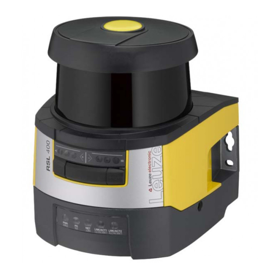
Page 13: Device Description
Connection unit PROFINET (CU400P-3M12) Optics cover Alphanumerical display (displayed) RSL 400 LED indicators Mini-B USB connection (behind protective cap) RSL 400 PROFINET LED indicators Fig. 3.1: Device overview of RSL 400 safety laser scanners with PROFIsafe interface Leuze electronic GmbH + Co. KG RSL 420P... -
Page 14: Device Overview
Additional output signals See description of the process data Number of changeover-capable protective/warning field pairs Four field mode (quads) Measurement data output optimized for vehicle naviga- Only RSL 455P tion USB interface Bluetooth interface Leuze electronic GmbH + Co. KG RSL 420P... -
Page 15: Protective Function Of Rsl 400 Safety Sensors
• Quick-release connection to the scanner unit for easy device swap-out (see "Quick Start Guide RSL 400"). NOTICE To ensure the IP protection and leak tightness of the devices, the supplied protection caps must always be placed on unused connections. Leuze electronic GmbH + Co. KG RSL 420P... - Page 16 • Four connections with M12 connectors / sockets for power and communication M12 connector, L-coded, voltage supply M12 socket, D-coded, PROFINET/PROFIsafe communication, input M12 socket, D-coded, PROFINET/PROFIsafe communication, output M12 socket, L-coded, voltage supply Fig. 3.3: Device with connection unit CU400P-4M12 Leuze electronic GmbH + Co. KG RSL 420P...
- Page 17 AIDA sockets, PROFINET, push-pull, 5-pin, voltage supply via copper cable AIDA socket, PROFINET, SCRJ push-pull, 2-pin, PROFINET/PROFIsafe communication via fiber-optic cable, in- AIDA socket, PROFINET, SCRJ push-pull, 2-pin, PROFINET/PROFIsafe communication via fiber-optic cable, out- Fig. 3.5: Device with connection unit CU400P-AIDA-OF Leuze electronic GmbH + Co. KG RSL 420P...
-
Page 18: Display Elements
RES activated and enabled Flashing Protective field occupied RES activated and blocked but ready to be unlocked Protective field free and linked sensor enabled (if applicable) Blue Free warning field Warning field interrupted Flashing Error Leuze electronic GmbH + Co. KG RSL 420P... -
Page 19: Led Indicator Of Profinet Connection Unit
PROFIsafe communication not initialized or switched off Green, Device in passive state or PROFINET wave function active flashing Green, Device on PROFIsafe active continuous light Red, flash- PROFIsafe configuration failed Red, con- PROFIsafe communication error tinuous light Leuze electronic GmbH + Co. KG RSL 420P... -
Page 20: Alphanumerical Display
SN: 21513123456 Sensor name / Network name Name of the sensor / network A123456789 IP: DHCP/FIX DHCP or permanent IP address IP: DHCP IP: 10.25.45.2 Bluetooth on/off Bluetooth detection ON/OFF Bluetooth ON Leuze electronic GmbH + Co. KG RSL 420P... - Page 21 In the case of blocking errors, the voltage supply must be separated and the cause of the error must be eliminated. Before switching on again, the steps taken before initial commissioning must be repeated (see chapter 10 "Starting up the device"). Leuze electronic GmbH + Co. KG RSL 420P...
-
Page 22: Field-Of-View Display
The loop guard for the optics cover prevents damage to the safety sensor caused by light contact with for- eign objects. The loop guard is available as an accessory (see chapter 18 "Order guide and accessories"). Leuze electronic GmbH + Co. KG RSL 420P... -
Page 23: Configuration And Diagnostic Software Sensor Studio
• You do not need the safety sensor to install the software on the PC. • All Windows applications are closed. NOTICE The software is installed in two steps: Ä Installing the Sensor Studio FDT frame. Ä Installing LeSafetyCollection device manager (DTM). Leuze electronic GmbH + Co. KG RSL 420P... - Page 24 RSL 400 device DTM. The password for the safety sensor only needs to be entered (i.e. the access level only needs to be changed) when the changes are downloaded to the safety sensor (see chapter 4.5.1 "Selecting access level"). Leuze electronic GmbH + Co. KG RSL 420P...
-
Page 25: User Interface
The device managers (DTM) of the safety sensors are created and managed in the FDT frame menu. Device manager DTM Configuration projects for setting up the selected safety sensor are created and managed in the device managers (DTM) of the safety sensors. Leuze electronic GmbH + Co. KG RSL 420P... -
Page 26: Fdt Frame Menu
Ä Start the Project Wizard in the FDT frame menu by clicking the button. NOTICE Information on the Project Wizard can be found in the online help for the FDT frame menu under Sensor Studio Options. Leuze electronic GmbH + Co. KG RSL 420P... -
Page 27: Dtm Change
Ä Save the configuration settings as a configuration project on the PC. You can open the configuration project again at later time via File > Open or with the Sensor Studio Project Wizard ( Leuze electronic GmbH + Co. KG RSL 420P... -
Page 28: Using Configuration Projects
RSL 400 PROFIsafe devices cannot be integrated in a configuration project using the integrated search function of the communication DTM. Ä Define the IP address of the PROFIsafe device using a different tool (e.g. PRONETA from Siemens). Leuze electronic GmbH + Co. KG RSL 420P... -
Page 29: Selecting Access Level
Selecting access level Using the device manager you can change the access level of the user if necessary. For the authorization concept of the software, see chapter 5.1 "Authorization concept of safety sensor". Leuze electronic GmbH + Co. KG RSL 420P... -
Page 30: Identification
Engineer. 4.5.5 DIAGNOSIS Adjustment / Alignment Display of safety sensor alignment using the integrated electronic spirit level Prerequisites: The software and safety sensor are connected. Leuze electronic GmbH + Co. KG RSL 420P... -
Page 31: Settings
You can only transfer changes made in the SETTINGS menu to the safety sensor if you are logged in with the access level Engineer. Communication • USB • DHCP • CONNECTION SETTINGS • Sensor data • Bluetooth • Activate Bluetooth module • Activate device scan • Bluetooth address Leuze electronic GmbH + Co. KG RSL 420P... - Page 32 Information on the display options can be found in the Sensor Studio configuration software in the informa- tion area and in the online help. Select the Help menu item in the menu [?]. Leuze electronic GmbH + Co. KG RSL 420P...
- Page 33 Information on the display options can be found in the Sensor Studio configuration software in the informa- tion area and in the online help. Select the Help menu item in the menu [?]. Leuze electronic GmbH + Co. KG RSL 420P...
-
Page 34: Functions
• Load the signed safety configuration from a file and transfer/download to the safety sensor • Transfer changed communication and diagnostics settings from the PC to the safety sensor • Print configuration data incl. protective/warning fields • Calibrate optics cover Leuze electronic GmbH + Co. KG RSL 420P... -
Page 35: Function Modes Of Safety Sensor
1 FP / 1 PF + 1 WF Fixed selection of one field pair 5 FP / 5 PF + 5 WF Selection by signal input: • Overlapped monitoring 10 FP / 10 PF + 10 WF Selection by signal input: • Fixed changeover moment Leuze electronic GmbH + Co. KG RSL 420P... -
Page 36: Selectable Resolution For Hand, Leg And Body Detection
The response time is the maximum time from a protective field violation to switch-off of the safety-related switching outputs. The response time is selected in the configuration project together for all protective/warning field pairs of a configuration bank. Leuze electronic GmbH + Co. KG RSL 420P... -
Page 37: Configurable Start-Up Behavior
The machine only starts when you press the reset button. Automatic restart The automatic restart function starts the machine automatically as soon as the protective field is free again. Leuze electronic GmbH + Co. KG RSL 420P... -
Page 38: Start/Restart Interlock (Res)
The safety sensor has the following modes for field pair activation and field pair changeover: • Fixed selection of one field pair • Selection by signal inputs with the changeover mode Overlapped monitoring • Selection by signal inputs with the changeover mode Fixed changeover moment Leuze electronic GmbH + Co. KG RSL 420P... - Page 39 G1 to G2 or G2 becomes active in addition to G1 (time overlap), an addi- tional protective field SFc must be connected which covers the areas SFa and SFb in an appropriate man- ner. Leuze electronic GmbH + Co. KG RSL 420P...
-
Page 40: Changeover Of Five Field Pairs In Changeover Mode Overlapped Monitoring
5.7.2 Changeover of five field pairs in changeover mode Overlapped monitoring Changeover mode Overlapped monitoring: This changeover mode is only permitted for up to five field pairs. Leuze electronic GmbH + Co. KG RSL 420P... -
Page 41: Changeover Of Ten Field Pairs In Changeover Mode Fixed Changeover Moment
The old field pair is monitored during the changeover time. • The previously active field pair is monitored during the changeover time. Leuze electronic GmbH + Co. KG RSL 420P... - Page 42 Initiation of the field pair changeover caused by a change in the signal – the old protective field is monitored until the end of the changeover time Fixed end – field pair changeover complete … Only one field pair change Field pair X X Field pair changeover Fig. 5.2: Signal/time diagram: Overlapped monitoring Leuze electronic GmbH + Co. KG RSL 420P...
-
Page 43: Monitoring Of Field Pair Changeover
• Field pair changeover active • Device functions • Error messages • Warnings • Diagnosis For an overview of all logic and electrical signals of the safety sensor, see chapter 16.4 "PROFIsafe status profile". Leuze electronic GmbH + Co. KG RSL 420P... -
Page 44: Applications
In accordance with EN ISO 13855, resolutions from 14 to 40 mm make sense here. This yields the necessary safety distance for finger protection, among others (see chapter 7.3 "Stationary point of operation guarding"). Leuze electronic GmbH + Co. KG RSL 420P... -
Page 45: Mobile Danger Zone Guarding
Protective field 1 for forward travel, deactivated Protective field 2 for forward travel, activated Protective field 1 for reverse travel, activated Protective field 2 for reverse travel, deactivated Warning field for reverse travel Fig. 6.2: Mobile danger zone guarding Leuze electronic GmbH + Co. KG RSL 420P... - Page 46 Protective field 1 for forward travel, deactivated Protective field 2 for forward travel, activated Protective field 1 for reverse travel, activated Protective field 2 for reverse travel, deactivated Warning field for reverse travel Fig. 6.3: Mobile danger zone guarding Leuze electronic GmbH + Co. KG RSL 420P...
-
Page 47: Danger Zone Safeguarding On Side-Tracking Skates
Protective and warning field pair for side guarding, left, activated Protective and warning field pair for side guarding, right, activated Protective and warning field pair for reverse travel, deactivated Fig. 6.4: Mobile side guarding on side-tracking skates Leuze electronic GmbH + Co. KG RSL 420P... -
Page 48: Mounting
= Response time of the protective device = Response time of the safety control = Stopping time of the machine = PROFIsafe watchdog time [mm] = Additional distance to the safety distance Leuze electronic GmbH + Co. KG RSL 420P... -
Page 49: Suitable Mounting Locations
• Make sure that the scanning range of the safety sensor is not limited. To mount the safety sensor tak- ing the scanning range into consideration, a template must be attached to the top cover of the safety sensor. Leuze electronic GmbH + Co. KG RSL 420P... - Page 50 Area with unobstructed view; must remain free Fig. 7.1: Mounting taking the scanning range of 270° into consideration all dimensions in mm Scan level Area with unobstructed view; must remain free (40 mm) Fig. 7.2: Mounting: area with unobstructed view Leuze electronic GmbH + Co. KG RSL 420P...
- Page 51 • Observe the information on the response times, the stopping time of the machine and the protective field dimensioning for your application. • Determine the size of the protective field on the basis of the mounting location, the calculated safety distances and additional distances. Leuze electronic GmbH + Co. KG RSL 420P...
-
Page 52: Mounting Examples
10 "Starting up the device"), and test (see chapter 12 "Testing") the safety sensor. 7.1.4 Mounting examples 54,6 all dimensions in mm Safety sensor Column BT856M mounting bracket Fig. 7.4: Example: mounting on a post Leuze electronic GmbH + Co. KG RSL 420P... - Page 53 Safety sensor BT840M mounting bracket Fig. 7.5: Example: mounting on a chamfered corner BTF815M mounting bracket (only in combination with the BTU800M mounting system) BTU800M mounting system Safety sensor Fig. 7.6: Example: mounting on floor Leuze electronic GmbH + Co. KG RSL 420P...
-
Page 54: Information On Protective Field Dimensioning
It must not be possible to walk behind unmonitored areas. Safety sensor Protective field Unmonitored area; Optimum availability at a distance of 50 mm to fixed contours Fig. 7.7: Unmonitored area Ä Prevent access to an unmonitored area with screens. Leuze electronic GmbH + Co. KG RSL 420P... - Page 55 Stepping behind protection by countersinking into the machine contour Ä Use a physical cover set at an angle over the safety sensor if you expect that the safety sensor will be used as a climbing aid or standing surface. Leuze electronic GmbH + Co. KG RSL 420P...
- Page 56 Shielding prevents reciprocal influencing of safety sensors set up beside one another Ä Install the safety sensors off-set on the height. Minimum distance, min. 100 mm Scan level Fig. 7.10: Height offset mounting, parallel alignment Leuze electronic GmbH + Co. KG RSL 420P...
-
Page 57: Stationary Danger Zone Guarding
If data is not available, you can commission Leuze to perform measurements; see chapter 15 "Service and support". Ä If an increase in the stopping time within the regular test periods is to be expected, take an additional time into account for the machine's stopping time t Leuze electronic GmbH + Co. KG RSL 420P... - Page 58 Largest protective field radius without additional distances, measured from the rotation axis of the rotary mirror Fig. 7.13: Defining the protective field contour for a stationary, horizontal protective field Ä Define the limits of the protective field using the safety distance S without an additional distance. Leuze electronic GmbH + Co. KG RSL 420P...
- Page 59 Ä Prevent obstructions within the calculated protective field boundaries. If this is not possible, implement protective measures so that the point of operation cannot be reached from out of the shadow of the ob- struction. Leuze electronic GmbH + Co. KG RSL 420P...
-
Page 60: Stationary Point Of Operation Guarding
• Detection of an adult's hand: • Resolution: 30 mm • Additional distance C : 128 mm • Arm detection: • Resolution: 40 mm • Additional distance C : 208 mm Leuze electronic GmbH + Co. KG RSL 420P... -
Page 61: Mobile Danger Zone Guarding On Agvs
A person lying on the floor can therefore be safely detected. This is required by standard EN ISO 3691-4 "Industrial trucks – Safety requirements and verification – Part 4: Driverless industrial trucks and their systems". Leuze electronic GmbH + Co. KG RSL 420P... -
Page 62: Minimum Distance D
Its size depends on the biggest radius R from the safety sensor mirror's rotary axis to the protective field boundary without Z . The position of the rotary mirror axis depends on the installation situation. Leuze electronic GmbH + Co. KG RSL 420P... -
Page 63: Protective Field Dimensions
Ä Arrange the protective field symmetrically with reference to the vehicle width, even if the safety sensor is not arranged centered. Leuze electronic GmbH + Co. KG RSL 420P... -
Page 64: Mobile Side Guarding On Agvs
Fig. 7.18: BTU800M mounting system NOTICE Floor mounting only with mounting system BTU800M Ä The mounting system BTU800M must be used in the case of installation using the mounting bracket for floor mounting. Leuze electronic GmbH + Co. KG RSL 420P... -
Page 65: Loop Guard
BTU800M mounting system Loop guard Safety sensor Fig. 7.19: Loop guard Ä Attach the safety sensor to the mounting system. Ä Engage the loop guard for the optics cover from above into the mounting system. Leuze electronic GmbH + Co. KG RSL 420P... -
Page 66: Electrical Connection
Ä Use suitable terminals. Ä Use heat-shrink tubing, wire-end sleeves or similar. NOTICE Protective Extra Low Voltage (PELV)! The device is designed in accordance with protection class III for supply with PELV (Protective Extra-Low Voltage). Leuze electronic GmbH + Co. KG RSL 420P... -
Page 67: Electrical Supply
Ä For permanent connection, connect the safety sensor to the Ethernet connection of the con- nection unit. Connection unit CU400P-3M12 M12 connector, A-coded, voltage supply, I/O signal RSL M12 socket, D-coded, PROFINET/PROFIsafe communication, input M12 socket, D-coded, PROFINET/PROFIsafe communication, output Fig. 8.1: Device with connection unit CU400P-3M12 Leuze electronic GmbH + Co. KG RSL 420P... - Page 68 Functional earth, communication cable shield. The shield of the intercon- nection cable is on the thread of the M12 socket. The thread is part of the metallic housing. The housing is at the same potential as functional earth. Leuze electronic GmbH + Co. KG RSL 420P...
-
Page 69: Connection Unit Cu400P-4M12
(e.g. for actuators). M12 connector, 5-pin, L-coded M12 socket, 5-pin, L-coded Fig. 8.5: Pin assignment M12 connector/socket, 5-pin, L-coded Tab. 8.3: Pin assignment for voltage supply Signal Comment 24 V DC (US1+) 0 V DC (US2-) 0 V DC (US1-) Leuze electronic GmbH + Co. KG RSL 420P... - Page 70 Functional earth, communication cable shield. The shield of the intercon- nection cable is on the thread of the M12 socket. The thread is part of the metallic housing. The housing is at the same potential as functional earth. Leuze electronic GmbH + Co. KG RSL 420P...
-
Page 71: Connection Unit Cu400P-Aida
• The current load of the connections must not exceed 16 A/pin. NOTICE Ä Lay the cables for the linear topology and the tap in the PROFINET controller in such a way that short circuits are prevented. Leuze electronic GmbH + Co. KG RSL 420P... - Page 72 Functional earth, communication cable shield. The shield of the communication cable is in contact with the housing of the AIDA socket. The housing is at the same potential as func- tional earth. Leuze electronic GmbH + Co. KG RSL 420P...
-
Page 73: Connection Unit Cu400P-Aida-Of
• The current load of the connections must not exceed 16 A/pin. NOTICE Ä Lay the cables for the linear topology and the tap in the PROFINET controller in such a way that short circuits are prevented. Leuze electronic GmbH + Co. KG RSL 420P... -
Page 74: Cable Lengths According To The Operating Voltage
Ä The operating voltage should not be allowed to drop below the recommended value if possi- ble. • The necessary operating voltage U must also ensure the function of the downstream devices in the case of a linear configuration. Leuze electronic GmbH + Co. KG RSL 420P... -
Page 75: Configuring The Safety Sensor
Ä For example, make sure that the distance range in which manipulation is possible cannot be accessed by personnel under normal operating conditions. Leuze electronic GmbH + Co. KG RSL 420P... - Page 76 To document the configuration, you can create a PDF file of the safety configuration or save the config- uration and settings in an *.xml file. Leuze electronic GmbH + Co. KG RSL 420P...
-
Page 77: Connecting Safety Sensor To Pc
• Connect the USB cable to the safety sensor and the PC. • Select the LAN / USB (RNDIS) interface for the device search. • Start the device search by clicking the [Start] button. • Select the safety sensor from the list of found devices. Leuze electronic GmbH + Co. KG RSL 420P... -
Page 78: Communication Between Safety Sensor And Pc
ð The mode selection of the Project Wizard is displayed. ð If the mode selection is not shown, click the [Project Wizard] button ( ) in the menu bar of the soft- ware to start the project wizard. Leuze electronic GmbH + Co. KG RSL 420P... - Page 79 The device manager (DTM) starts without querying the access level of the user. During commu- nication with the safety sensor, the safety sensor does however query the access level of the user. To change the access levels, see chapter 9.8 "Selecting access level". Leuze electronic GmbH + Co. KG RSL 420P...
-
Page 80: Configuring Protective Function
The changeover-capable protective/warning field pairs for the selected protective function are defined in configuration banks. The configuration banks are shown in the navigation tree of the configuration menu as "Bank", e.g. Bank A1. Leuze electronic GmbH + Co. KG RSL 420P... - Page 81 [Close]. ð The added field pairs are shown in the CONFIGURATION menu as an option under Bank 1 under Pro- tective function_A. The Parameters option is displayed for each field pair. Leuze electronic GmbH + Co. KG RSL 420P...
- Page 82 It is also possible to read in an RS4 configuration file as well as to convert the protective fields on the RSL 400. Note here, that the converted field pairs are only contour suggestions. Therefore, check that the fields are appropriate for the requirements of your safety application. Leuze electronic GmbH + Co. KG RSL 420P...
-
Page 83: Configuring Field Pair Monitoring
Ä In the CONFIGURATION menu or in the SETTINGS menu, click the [Save configuration and settings to file] button. Ä Determine the storage location and the name of the configuration file. Ä Click [Save]. ð The configuration and settings are saved in the file format *.xml. Leuze electronic GmbH + Co. KG RSL 420P... -
Page 84: Transferring Configuration Project To Safety Sensor
Confirm with [OK]. Ä Before downloading the safety configuration, check whether you are connected to the correct safety sensor. Confirm the displayed safety notice with [Yes]. Fig. 9.3: Check before safety configuration is downloaded Leuze electronic GmbH + Co. KG RSL 420P... - Page 85 Fig. 9.4: Confirmation: safety configuration downloaded NOTICE The safety-related switching outputs will already have switched on if all conditions are fulfilled. ð The software has saved the configuration project in the safety sensor. Leuze electronic GmbH + Co. KG RSL 420P...
-
Page 86: Selecting Access Level
Ä In the DTM menu bar, click the [Reset safety configuration] button. ð Users with the access level Engineer can additionally transfer the changed safety configuration to the safety sensor (see chapter 9.7 "Transferring configuration project to safety sensor"). Leuze electronic GmbH + Co. KG RSL 420P... -
Page 87: Starting Up The Device
Ä Unlock the start/restart interlock using the reset button. The safety-related switching signals are only enabled if you hold down the reset button for between 0.12 s and 4 s. Leuze electronic GmbH + Co. KG RSL 420P... -
Page 88: Shutting Down
Ä Change the configuration parameters of the safety sensor using the configuration and diag- nostic software according to the operating range of the replacement scanner unit. Leuze electronic GmbH + Co. KG RSL 420P... - Page 89 Ä If you transferred a new configuration to the safety sensor, check the safety sensor according to the routine for initial start-up (see chapter 12.1.1 "Checklist for integrator – to be performed prior to the ini- tial start-up and following modifications"). Leuze electronic GmbH + Co. KG RSL 420P...
-
Page 90: Profisafe And Profinet
• Subnet mask: 255.255.255.0 Electrical connection For the electrical connection of the supply voltage and the interface, M12 connectors/sockets or AIDA push/pull connectors/sockets are mounted on the device (see chapter 8 "Electrical connection"). Leuze electronic GmbH + Co. KG RSL 420P... -
Page 91: Gsdml File
Ä CU 4M12: connection unit with L-coded M12 connectors/sockets for the voltage supply Ä CU AIDA: connection unit with push-pull connectors/sockets for copper cables Ä CU AIDA OF: connection unit with push-pull connectors/sockets for fiber-optic cables Leuze electronic GmbH + Co. KG RSL 420P... - Page 92 Ä Enter the type designation or part number of the device as the search term. Ä The GSDML files can be found on the product page for the device under the Downloads tab. Leuze electronic GmbH + Co. KG RSL 420P...
-
Page 93: Integrating In A Profisafe Network
Ä Set the PROFIsafe parameters. Tab. 11.1: PROFIsafe parameters Parameter Meaning Setting F_SIL Safety integration level of the safety laser SIL2 (not changeable) scanner F_Block_ID ’0’ (not changeable) F_Par_Version PROFIsafe operating mode ’0’ (not changeable) Leuze electronic GmbH + Co. KG RSL 420P... -
Page 94: Configuring For The Siemens Tia Portal
Ä Connect the supply voltage (typ. +24 V DC). ð The RSL 400 PROFIsafe starts up. 11.4.2 Prepare the control Ä Assign the IO controller of the control an IP address. Ä Prepare the control for consistent data transmission. Leuze electronic GmbH + Co. KG RSL 420P... -
Page 95: Install The Gsdml File
GSDML file. Ä Load the GSDML file for the configuration of the safety laser scanner (see chapter 11.4.5 "Load the de- vice description file (GSDML file)"). Leuze electronic GmbH + Co. KG RSL 420P... -
Page 96: Start Tia Portal
Ä Start the TIA portal and open an existing project with the configured control (PLC). Ä Select the Devices & Networks option. Ä Select the configured PLC with a double-click. ð The device view dialog is displayed Leuze electronic GmbH + Co. KG RSL 420P... -
Page 97: Load The Device Description File (Gsdml File)
In the project navigation, select Devices & Networks and select the Network view tab. Ä Open the hardware catalog. Double-click to select Other field devices > Profinet IO > Sensors > Leuze electronic GmbH+Co.KG > Leuze > RSL400P. Leuze electronic GmbH + Co. KG... -
Page 98: Connect The Rsl 400P To The Control
Port of the PLC NOTICE Ä Make certain that the correct PLC port is selected if multiple ports are configured in the PLC. ð The RSL 400P is connected to the PLC via PROFINET-IO. Leuze electronic GmbH + Co. KG RSL 420P... -
Page 99: Add Safety Module
Ä If necessary, insert other non-safety-oriented PROFINET modules. Expand the Device data dialog box in the device view. You can only insert PROFINET modules that are listed under the Device overview tab. Leuze electronic GmbH + Co. KG RSL 420P... -
Page 100: Configure Rsl400P Header Module
Ä On the Device overview tab, select the RSL400P module. Perform the configuration via Properties > General. Ä Set the Ethernet addresses and the PROFINET device names. • Assign each IP address a unique PROFINET device name. Leuze electronic GmbH + Co. KG RSL 420P... -
Page 101: Configure The Safety Module
Default PROFIsafe parameters in the GSDML file The GSDML file defines the default values for the PROFIsafe parameters. The default values are used if the PROFIsafe parameters were not modified when configuring. Leuze electronic GmbH + Co. KG RSL 420P... -
Page 102: Conclude Configuration
The switch functionality of the PROFINET connection continues to exist. 11.5.1 Project modules for DAP 1 Modules [M1] … [M8] • For devices with M12 connection unit (CU M12): • DeviceID: 0x0011 Leuze electronic GmbH + Co. KG RSL 420P... - Page 103 Detailed status of protective function A PROTECTIVE_FUNC- TION_A_STATUS see chapter 11.5.7 "Module [M5] – PROTECTIVE_FUNC- TION_A_STATUS" [M6] Detailed status of protective function B PROTECTIVE_FUNC- TION_B_STATUS see chapter 11.5.8 "Module [M6] – PROTECTIVE_FUNC- TION_B_STATUS" Leuze electronic GmbH + Co. KG RSL 420P...
-
Page 104: Project Modules For Dap 2
11.5.12 "Module [M11] ‑ SAFE_SIGNAL_PS2V6" [M12] General information on the status of the de- vice and safety functions. SYSTEM_STATUS Simple system diagnostics is possible. see chapter 11.5.13 "Module [M12] ‑ SYSTEM_STATUS" Leuze electronic GmbH + Co. KG RSL 420P... - Page 105 11.5.17 "Module [M16] – PROTECTIVE_FUNC- TION_A_VIOLATION" [M17] Information on protective field interruption or warning field interruption of protective PROTECTIVE_FUNC- function B TION_B_VIOLATION see chapter 11.5.18 "Module [M17] – PROTECTIVE_FUNC- TION_B_VIOLATION" Leuze electronic GmbH + Co. KG RSL 420P...
-
Page 106: Module [M1] - Safe_Signal
Status of active SIGNE protective field - protective func- tion A B-WF-VIO FREE Status of active SIGNE warning field - pro- tective function B B-PF-VIO FREE Status of active SIGNE protective field - protective func- tion B Leuze electronic GmbH + Co. KG RSL 420P... - Page 107 Collective mes- sage sage: fault de- tected by field pair selection monitor- MODE-PARK NOT PARKE Park request ful- PARKE filled Status of local out- put 1 Status of local out- put 2 Reserve4 Reserve5 Leuze electronic GmbH + Co. KG RSL 420P...
- Page 108 Function mode: one protective function, 10 field pairs Byte in safe Byte in Data type Signal name Safe Description telegram module 0 … 4 Field pair selection 5 … 7 Reserve 0 … 7 Reserve 0 … 1 Start signals 2 … 6 Reserve Start/stop data recorder Leuze electronic GmbH + Co. KG RSL 420P...
-
Page 109: Module [M2] - System_Status
Park request ful- PARKED filled Reserve1 Reserve2 Reserve3 0 … 15 Int16 ALIGNMENT- Horizontal align- ment of the spirit level 0 … 15 Int16 ALIGNMENT- Vertical alignment of the spirit level 0 … 15 Int16 SYS-TEMP System tempera- ture Leuze electronic GmbH + Co. KG RSL 420P... -
Page 110: Module [M3] - Scan_Number
• The module indicates whether the protective field or warning field is free or occupied at a certain angle. • In addition, the module indicates which field pair is selected for protective function A and whether the active field pair corresponds to a predefined field pair. Leuze electronic GmbH + Co. KG RSL 420P... - Page 111 SEL 3 pair A (numbers 1 - 10); superim- posed field Reserve1 Reserve2 A-FP-SEL-1 Defined field pair LECTED selected – Protec- tive function A A-FP-SEL-2 Defined field pair LECTED selected – Protec- tive function A Leuze electronic GmbH + Co. KG RSL 420P...
-
Page 112: Module [M6] - Protective_Function_B_Status
- protec- tive function B Reserve0 0 … 3 B-PAIR- First selected field SEL 1 pair B (numbers 1 - 10) 4 … 7 B-PAIR- Second selected SEL 2 field pair B (num- bers 1 - 10); super- imposed field Leuze electronic GmbH + Co. KG RSL 420P... -
Page 113: Module [M7] - Protective_Function_A_Violation
-135 ° … +135 ° 0 … 15 uInt16 A-WF-VIO- Distance of the RADIUS first beam with warning field viola- tion in the direction of rotation for warning field 0 mm … 20000 m Leuze electronic GmbH + Co. KG RSL 420P... -
Page 114: Module [M11] - Safe_Signal_Ps2V4
The module defines the safe input and output signals of the RSL 400 PROFIsafe: • The protective fields and configuration banks are changed over via the output signals. • The output signals contain the start signals for releasing a manual (re-)start. Leuze electronic GmbH + Co. KG RSL 420P... - Page 115 Byte in Data Signal name Value Value Safe Description safe module type ‘0‘ ‘1‘ tele- gram 0 … 5 0 … 5 0 … 7 Byte Output data ac- cording to the func- tion mode 0 … 7 Byte Reserve Leuze electronic GmbH + Co. KG RSL 420P...
-
Page 116: Module [M11] - Safe_Signal_Ps2V6
• The output signals contain the start signals for releasing a manual (re-)start. • The input data contains the safe switching signals for the protective fields and warning fields of the RSL 400 PROFIsafe. Leuze electronic GmbH + Co. KG RSL 420P... - Page 117 ‘1‘ tele- gram 0 … 5 0 … 5 0 … 7 Byte Output data ac- cording to the func- tion mode 0 … 7 Byte Profisafe sta- PROFIsafe status 0 … 7 Byte CrcHH PROFIsafe Crc 0 … 7 Byte CrcHL Crc PROFIsafe Leuze electronic GmbH + Co. KG RSL 420P...
- Page 118 Reserve 0 … 7 Byte Reserve 0 … 7 Byte Reserve Start/restart signal TIVE for warning field - protective func- tion A Start/restart signal TIVE for protective field - protective func- tion A 2 … 7 Reserve 0 … 7 Byte Reserve Leuze electronic GmbH + Co. KG RSL 420P...
-
Page 119: Module [M12] - System_Status
Contamination dis- sage play for optics cover (Warning and switch-off) FIELD PAIR Mes- Collective mes- sage sage for field pair changeover error MODE-PARK NOT PARKE Park mode con- PARKE firmed 5 … 7 Reserve Leuze electronic GmbH + Co. KG RSL 420P... -
Page 120: Module [M13] - System_Data
• Submodule ID: 0x0000000D Description The module contains the current data of the internal spirit level for aligning the device. The module also contains the data of the inside temperature and the applied supply voltage. Leuze electronic GmbH + Co. KG RSL 420P... -
Page 121: Module [M14] - Protective_Function_A_Status
- protective function 2 … 3 Reserve A-ACTIVE Protective func- TIVE tion A active / con- figured 5 … 7 Reserve A-RES-WF Start/restart active TIVE (warning field A) A-RES Start/restart active TIVE (protective field A) 2 … 7 Reserve Leuze electronic GmbH + Co. KG RSL 420P... - Page 122 CU firmware/hard- ware version E2) A-FP-SEL-1 Defined field pair LECTE selected 1 - pro- tective function A A-FP-SEL-2 Defined field pair LECTE selected 2 - pro- tective function A 2 … 7 Reserve 0 … 7 Byte Reserve Leuze electronic GmbH + Co. KG RSL 420P...
-
Page 123: Module [M15] - Protective_Function_B_Status
2 … 7 Reserve B-PF-VIO- FREE Status of active SEG-1 SIGNE protective field segment 1 - pro- tective function B B-PF-VIO- FREE Status of active SEG-2 SIGNE protective field segment 2 - pro- tective function B 2 … 7 Reserve Leuze electronic GmbH + Co. KG RSL 420P... -
Page 124: Module [M16] - Protective_Function_A_Violation
Value Safe Description non-safe mod- type ‘0‘ ‘1‘ telegram 0 … 15 int16 A-WF-VIO- Angle of the first ANGLE beam with warning field violation in the direction of ro- tation for warning field -135 ° … +135 ° Leuze electronic GmbH + Co. KG RSL 420P... -
Page 125: Module [M17] - Protective_Function_B_Violation
-135 ° … +135 ° 0 … 15 uint16 B-WF-VIO- Distance of the RADIUS first beam with warning field viola- tion in the direc- tion of rotation for warning field 0 mm … 20000 m Leuze electronic GmbH + Co. KG RSL 420P... -
Page 126: Status Messages Of The Profinet Stack
A valid configuration was loaded in the device for the first time. The system switches to monitoring mode. NOTICE You can find further information on PROFINET status message in the description of the PROFINET device protocol. Leuze electronic GmbH + Co. KG RSL 420P... -
Page 127: Testing
Ä If you answer one of the items on the check list with no, the machine must no longer be op- erated (see table below). Ä EN IEC 62046 contains additional recommendations on testing protective devices. Leuze electronic GmbH + Co. KG RSL 420P... - Page 128 Are settings that could result in an unsafe state possible only by means of key, password or tool? Are there incentives that pose stimulus for tampering? Were the operators instructed prior to starting work? Leuze electronic GmbH + Co. KG RSL 420P...
-
Page 129: To Be Performed Periodically By Competent Persons
Ä Make certain that there are no people in the danger zone. Ä Before they begin work, train the operators on their respective tasks and provide suitable test objects and an appropriate test instruction. Leuze electronic GmbH + Co. KG RSL 420P... -
Page 130: Checklist - Periodically By The Operator
– are the obviously dangerous machine parts stopped with- out noticeable delay? Protective device with presence detection: the protective field is interrupted with the test object – does this prevent operation of the obviously dangerous machine parts? Leuze electronic GmbH + Co. KG RSL 420P... -
Page 131: Diagnosis And Troubleshooting
Application error • E (External) External fault • F (Failure) internal device error • Switch-off of the safety-related switching signals • Self test unsuccessful • Hardware error • P (Parameter) Inconsistency in configuration Leuze electronic GmbH + Co. KG RSL 420P... - Page 132 Swap out the safety sensor or change the known field pair selection parameter. configuration. The type of safety sensor must be the same as the type stored in the connec- tion unit or in the Sensor Studio software. Leuze electronic GmbH + Co. KG RSL 420P...
- Page 133 Check the release signal for field pair changeover or change the safety configura- tion. U0793 Field pair changeover without request. Check the request signal for field pair changeover or change the safety configura- tion. Leuze electronic GmbH + Co. KG RSL 420P...
- Page 134 (Without switch-off of the safety-related switching signals) I1018 Internal temperature is normal again. The safety sensor is in the specified tempera- ture range and in normal operation. Leuze electronic GmbH + Co. KG RSL 420P...
- Page 135 F..The monitoring functions have detected an Create the service file (see chapter 4.5.5 "DI- internal error. AGNOSIS") and contact the Leuze customer service (see chapter 15 "Service and sup- port"). Leuze electronic GmbH + Co. KG RSL 420P...
-
Page 136: Care, Maintenance And Disposal
Guide RSL 400". Ä Undo the quick-release fasteners on both sides of the scanner unit. Ä Pull the scanner unit off the connection unit. Ä Place the new scanner unit on the connection unit. Leuze electronic GmbH + Co. KG RSL 420P... -
Page 137: Cleaning The Optics Cover
After cleaning is complete, the safety sensor resets itself auto- matically. Ä Clean the optics cover over the entire 360° range. Ä Soak cloth with cleaning agent. Ä Wipe optics cover free in one swipe. Leuze electronic GmbH + Co. KG RSL 420P... -
Page 138: Servicing
Ä For repairs, contact your responsible Leuze subsidiary or Leuze customer service (see chapter 15 "Ser- vice and support"). 14.4 Disposing Ä For disposal observe the applicable national regulations regarding electronic components. Leuze electronic GmbH + Co. KG RSL 420P... -
Page 139: Service And Support
Contact & Support > Repair Service & Returns. To ensure quick and easy processing of your request, we will send you a returns order with the returns ad- dress in digital form. Leuze electronic GmbH + Co. KG RSL 420P... -
Page 140: Technical Data
Tab. 16.4: Protective field range Device range Resolution [mm] Protective field range [m] 3.00 4.50 6.25 8.25 3.00 4.50 6.25 8.25 3.00 4.50 6.25 8.25 3.00 4.50 6.25 6.25 3.00 4.50 4.50 4.50 Leuze electronic GmbH + Co. KG RSL 420P... - Page 141 1.0 A Power consumption RSL 4xxP with CU400P-3M12, CU400P-4M12 or CU400P-AIDA: 22 W RSL 4xxP with CU400P-AIDA-OF: 24 W Switch-on current Max. 2 A Overvoltage protection overvoltage protection with protected limit stop Protective conductor Connection required Leuze electronic GmbH + Co. KG RSL 420P...
- Page 142 Conformance class Class C Network load class Class III Security level Security level 1 Switch IRT-ready 2-port switch acc. to IEEE 802; integrated in connection unit Port properties Auto-Negotiation Auto-Polarity Auto-Crossover I&M I&M 0 - 4 Leuze electronic GmbH + Co. KG RSL 420P...
- Page 143 Weight of standard version incl. connection unit Approx. 3 kg Distance, beam level center to bottom housing edge 104 mm Tab. 16.16: Patents US patents US 7,656,917 B US 7,696,468 B US 8,520,221 B US 2016/0086469 A Leuze electronic GmbH + Co. KG RSL 420P...
-
Page 144: Dimensions
Technical data 16.2 Dimensions all dimensions in mm Fig. 16.1: Dimensions of safety laser scanner with CU400P-3M12 connection unit Leuze electronic GmbH + Co. KG RSL 420P... - Page 145 Technical data all dimensions in mm Fig. 16.2: Dimensions safety laser scanner with connection unit CU400P-4M12, CU400P-AIDA or CU400P-AIDA- Leuze electronic GmbH + Co. KG RSL 420P...
-
Page 146: Dimensioned Drawings: Accessories
Reference point for distance measurement and protective field radius Fig. 16.3: Dimensions of scanning range 16.3 Dimensioned drawings: Accessories 157,5 166,3 all dimensions in mm Fig. 16.4: BTU800M mounting system Leuze electronic GmbH + Co. KG RSL 420P... - Page 147 Technical data Leuze electronic GmbH + Co. KG RSL 420P...
- Page 148 Technical data all dimensions in mm Cable fastening Adjustable scanning height: 75 mm – 375 mm Fig. 16.5: Bracket for floor assembly BTF815-30M Leuze electronic GmbH + Co. KG RSL 420P...
- Page 149 Technical data all dimensions in mm Fig. 16.6: BTF815M mounting bracket Leuze electronic GmbH + Co. KG RSL 420P...
- Page 150 Technical data all dimensions in mm Fig. 16.7: BTF830M mounting bracket Leuze electronic GmbH + Co. KG RSL 420P...
- Page 151 Technical data all dimensions in mm Fig. 16.8: Loop guard BTP800M 205,2 all dimensions in mm Fig. 16.9: BT840M mounting bracket Leuze electronic GmbH + Co. KG RSL 420P...
- Page 152 Technical data all dimensions in mm Fig. 16.10: Mounting bracket BT840M, view A 233,5 all dimensions in mm Fig. 16.11: BT856M mounting bracket Leuze electronic GmbH + Co. KG RSL 420P...
-
Page 153: Profisafe Status Profile
• DeviceID: 0x0013 • Textual designation for configuration: RSL400P AIDA-OF • For devices with connection unit with L-coded M12 connectors/sockets for the voltage supply (CU 4M12): • DeviceID: 0x0016 • Textual designation for configuration: RSL400P 4M12 Leuze electronic GmbH + Co. KG RSL 420P... - Page 154 11.5.9 "Module [M7] – PROTECTIVE_FUNC- TION_A_VIOLATION" [M8] Information on protective field interruption or warning field interruption of protective PROTECTIVE_FUNC- function B TION_B_VIOLATION see chapter 11.5.10 "Module [M8] – PROTECTIVE_FUNC- TION_B_VIOLATION" Leuze electronic GmbH + Co. KG RSL 420P...
-
Page 155: Project Modules For Dap 2
Detailed status of protective function A PROTECTIVE_FUNC- TION_A_STATUS see chapter 11.5.15 "Module [M14] – PROTECTIVE_FUNC- TION_A_STATUS" [M15] Detailed status of protective function B PROTECTIVE_FUNC- TION_B_STATUS see chapter 11.5.16 "Module [M15] – PROTECTIVE_FUNC- TION_B_STATUS" Leuze electronic GmbH + Co. KG RSL 420P... - Page 156 11.5.17 "Module [M16] – PROTECTIVE_FUNC- TION_A_VIOLATION" [M17] Information on protective field interruption or warning field interruption of protective PROTECTIVE_FUNC- function B TION_B_VIOLATION see chapter 11.5.18 "Module [M17] – PROTECTIVE_FUNC- TION_B_VIOLATION" Leuze electronic GmbH + Co. KG RSL 420P...
-
Page 157: Standards And Legal Regulations
• EN ISO 13849-1, -2 • IEC/EN 61508-1 to -7 • EN IEC 62061 • IEC/EN 60204-1 • EN ISO 13849-1 • EN ISO 13855 • EN IEC 61496-3 • EN ISO 3691-4 • EN IEC 62046 • IEC 61158 • IEC 61784 • IEC 61784-3-3 • IEC 61076-3-117 • ISO/IEC 61754-24-2 Leuze electronic GmbH + Co. KG RSL 420P... -
Page 158: Order Guide And Accessories
8.25 m, PROFIsafe PROFINET: 2x push-pull connector for copper cables 53800308 RSL420P-S/CU400P- 1 safety-related switching signal; 10 field pairs; protective field AIDA-OF range max. 3.0 m, PROFIsafe PROFINET: 2x push-pull connector for fiber-optic cables Leuze electronic GmbH + Co. KG RSL 420P... - Page 159 Connection cable, 5-pin, 25 m 50129553 CB-M12-30000E-5GF Connection cable, 5-pin, 30 m Connection technology – RJ45 interconnection cables 50135080 KSS ET-M12-4A-RJ45- Interconnection cable RJ45, 2 m A-P7-020 50135081 KSS ET-M12-4A-RJ45- Interconnection cable RJ45, 5 m A-P7-050 Leuze electronic GmbH + Co. KG RSL 420P...
- Page 160 Cleaning fluids 430400 Cleaning set 1 Cleaning fluid for plastic, 150 ml, cleaning cloths, 25x, soft, fuzz- free 430410 Cleaning set 2 Cleaning fluid for plastic, 1,000 ml, cleaning cloths, 100x, soft, fuzz- free Leuze electronic GmbH + Co. KG RSL 420P...
-
Page 161: Ec Declaration Of Conformity
EC Declaration of Conformity EC Declaration of Conformity The safety laser scanners of the RSL 400 series have been developed and manufactured in accordance with the applicable European standards and directives. Leuze electronic GmbH + Co. KG RSL 420P...
Need help?
Do you have a question about the RSL 420P and is the answer not in the manual?
Questions and answers