
Related Manuals for Leuze electronic ROTOSCAN RS4


Summary of Contents for Leuze electronic ROTOSCAN RS4
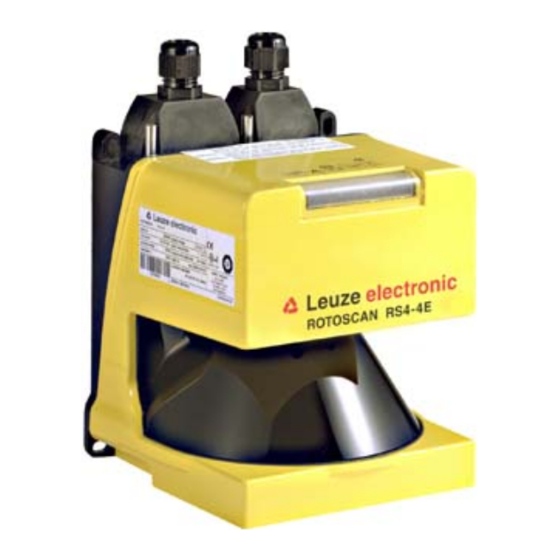
- Page 1 ROTOSCAN RS4 Safety Laser Scanners O r i g i n a l o p e r a t i n g i n s t r u c t i o n s Buy: www.ValinOnline.com | Phone 844-385-3099 | Email: CustomerService@valin.com...
-
Page 2: Table Of Contents
Machine response times, stopping time ........................33 6.4.4 Protective field and reference boundary ........................34 Stationary access guarding ............................34 6.5.1 Safety distance "S" ..............................35 6.5.2 Machine response times, stopping time ........................35 Leuze electronic Buy: www.ValinOnline.com | Phone 844-385-3099 | Email: CustomerService@valin.com... - Page 3 9.4.7 Ambient influences additional distance........................57 9.4.8 Speed with PF ................................58 9.4.9 Braking distance with PF ............................58 9.4.10 Standstill monitoring ..............................58 9.4.11 Creep and reverse ..............................58 Leuze electronic Buy: www.ValinOnline.com | Phone 844-385-3099 | Email: CustomerService@valin.com...
- Page 4 LED warning and error displays..........................72 13.4 Diagnostics codes............................... 73 Repairs ..................................78 14.1 Change the front screen ............................. 78 Disposing ..................................81 Service ..................................82 Accessories ................................83 17.1 Accessories to choose from............................83 Leuze electronic Buy: www.ValinOnline.com | Phone 844-385-3099 | Email: CustomerService@valin.com...
-
Page 5: About This Document
Safe parametering Art. no. 607143** uring the safety sensor (Software RS4soft instruc- Included with the product tions) delivery on CD-ROM Additional information on ROTOSCAN RS4/AS-i Additional information Art. no. 607060** for the ROTOSCAN Included with the product RS4-4 connecting and... -
Page 6: Safety
The responsibility for the safety-assured use of the safety sensor and compliance with the regulations and directives that apply in the country of use lies with the machine's manufacturer and company operating the machine. Leuze electronic Buy: www.ValinOnline.com | Phone 844-385-3099 | Email: CustomerService@valin.com... -
Page 7: Laser
Observe all technical data and ambient conditions. Industrial use only The safety sensor is not suitable for residential areas, because it can cause radio interferences. Only use the safety sensor in industrial environments. Leuze electronic Buy: www.ValinOnline.com | Phone 844-385-3099 | Email: CustomerService@valin.com... -
Page 8: Guarantee The Availability Of The Safety Sensor
The type and content of the information may not, however, result in any questionable safety-related actions by the user. Where required, safety key, special tools and passwords should be maintained under the control of one or more responsible or authorized people. Leuze electronic Buy: www.ValinOnline.com | Phone 844-385-3099 | Email: CustomerService@valin.com... -
Page 9: Exemption Of Liability
Safety Exemption of liability Leuze electronic GmbH + Co. KG is not liable in the following cases: • safety sensor is not used as intended • safety notices are not adhered to • reasonably foreseeable misuse is not taken into account •... -
Page 10: Device Description
Device description Device description The ROTOSCAN RS4 safety sensor is an optical, two-dimensional measuring Safety Laser Scanner. The safety sensor transmits periodic light pulses via a rotating deflection unit. The light pulses are reflected by obstructions, e.g. people, and received by the safety sensor again and analyzed. The safety sensor calculates the precise position of the obstruction from the light travel time and the angle of the deflection unit at that time. -
Page 11: Device Overview
X2 interfaces for PC/laptop, with protective cap Status display Scatter screens Front screen Figure 3.2: Safety sensor overview Display elements Status display Five LEDs on the front show the safety sensor's status Leuze electronic Buy: www.ValinOnline.com | Phone 844-385-3099 | Email: CustomerService@valin.com... - Page 12 Device description Figure 3.3: Status displays Leuze electronic Buy: www.ValinOnline.com | Phone 844-385-3099 | Email: CustomerService@valin.com...
-
Page 13: Mounting System (Option)
The ConfigPlug makes it easier to swap out the safety sensor. It saves the configuration when the PC is configured and automatically transfers it with the device swap-out to the replacement device. The Config- Plug is available as an accessory (see chapter 17.1 „Accessories to choose from“). Leuze electronic Buy: www.ValinOnline.com | Phone 844-385-3099 | Email: CustomerService@valin.com... -
Page 14: Functions
• It is not possible to walk behind or go around the effective protective field. Allow for an optical and/or acoustic start warning. 4.3.1 Automatic start The automatic start function starts the machine automatically as soon as the supply voltage is present. Leuze electronic Buy: www.ValinOnline.com | Phone 844-385-3099 | Email: CustomerService@valin.com... -
Page 15: Automatic Restart
80 ms. • The switchover process performed by the control system must agree with the safety sensor's config- uration. This configuration is specified with the configuration and diagnostics software. Leuze electronic Buy: www.ValinOnline.com | Phone 844-385-3099 | Email: CustomerService@valin.com... -
Page 16: Reference Boundary Monitoring
Two further functions are integrated into the MotionMonitoring function, which are assigned to the two field pairs, 7 and 8: • Further travel blocking – field pair 7 • Creep and reverse – field pair 8 Leuze electronic Buy: www.ValinOnline.com | Phone 844-385-3099 | Email: CustomerService@valin.com... - Page 17 • If the speed increases further or if the maximum speed is exceeded, the safety sensor switches off the safety-related switching outputs; an entry appears in the diagnostics list. Leuze electronic Buy: www.ValinOnline.com | Phone 844-385-3099 | Email: CustomerService@valin.com...
-
Page 18: Applications
EMERGENCY STOP command device and start/restart button Safety sensor Protective field 2, activated Protective field 1, deactivated Warning field 2, activated Warning field 1, deactivated Figure 5.1: Stationary danger zone guarding with two alternating work areas Leuze electronic Buy: www.ValinOnline.com | Phone 844-385-3099 | Email: CustomerService@valin.com... -
Page 19: Stationary Point Of Operation Guarding
Reference boundaries of both protective fields EMERGENCY STOP command device and start/restart button Protective field 1, activated Protective field 2, deactivated Figure 5.2: Stationary point of operation guarding with protective field switchover Leuze electronic Buy: www.ValinOnline.com | Phone 844-385-3099 | Email: CustomerService@valin.com... -
Page 20: Stationary Access Guarding
This is why the start/restart inter- lock function is vital for access guarding. Safety sensor Reference boundary of the protective field EMERGENCY STOP command device and start/restart button Protective field Figure 5.3: Stationary access guarding Leuze electronic Buy: www.ValinOnline.com | Phone 844-385-3099 | Email: CustomerService@valin.com... -
Page 21: Mobile Danger Zone Guarding
Protective field 1 for forward travel, activated Warning field 1 for forward travel, activated Protective field 2 for curved stretch, left, deactivated Protective field 3 for curved stretch, right, deactivated Figure 5.4: Mobile danger zone guarding Leuze electronic Buy: www.ValinOnline.com | Phone 844-385-3099 | Email: CustomerService@valin.com... -
Page 22: Mobile Side Guarding
Protective field and warning field pair for side guarding, right, activated Protective field and warning field pair for side guarding, left, activated Figure 5.5: Mobile side guarding on side-tracking skates Leuze electronic Buy: www.ValinOnline.com | Phone 844-385-3099 | Email: CustomerService@valin.com... -
Page 23: Mounting
If there is a risk that the safety sensor will be used as a climbing aid, install a suitable physical cover over the safety sensor. Ensure that machine parts, protective grids or covers do not impair the safety sensor's field of vision. Leuze electronic Buy: www.ValinOnline.com | Phone 844-385-3099 | Email: CustomerService@valin.com... -
Page 24: Basic Infos On The Protective Field Dimensioning
Unmonitored area Figure 6.1: Protective field shape – unmonitored areas Prevent access to an unmonitored area with screens. Prevent walking behind by countersinking the safety sensor into the machine contour. Leuze electronic Buy: www.ValinOnline.com | Phone 844-385-3099 | Email: CustomerService@valin.com... -
Page 25: Protective Field Setup With Adjacent Safety Sensors
If you plan for a shielding that is still within the countersinking in the machine contour, the resolution of the protective fields must not be impaired at any accessible points. You require the reciprocal shielding with both horizontal and vertical alignment of the protective fields. Leuze electronic Buy: www.ValinOnline.com | Phone 844-385-3099 | Email: CustomerService@valin.com... - Page 26 Install the safety sensors off-set on the height. Figure 6.4: Height offset installation, parallel alignment Install the safety sensors with crossed alignment. Figure 6.5: Installation beside one another, without height offset, crossed alignment Leuze electronic Buy: www.ValinOnline.com | Phone 844-385-3099 | Email: CustomerService@valin.com...
-
Page 27: Stationary Danger Zone Guarding
Configure the protective field so that the safety-related switching outputs are switched off from every accessible point with sufficient minimum distance "D". Mark the protective field boundaries on the floor. You can easily test the safety sensor along this marking. Leuze electronic Buy: www.ValinOnline.com | Phone 844-385-3099 | Email: CustomerService@valin.com... -
Page 28: Beam Level Height
Safety sensor response time in s Safety interface device response time in s, if used Machine stopping time plus addition for deterioration in s Additional distance because of the possibility of reaching over in mm Leuze electronic Buy: www.ValinOnline.com | Phone 844-385-3099 | Email: CustomerService@valin.com... -
Page 29: Additional Distance "C" Because Of The Possibility Of Reaching Over
Determine the machine/system's stopping time T If data is not available, you can commission Leuze electronic to perform measurements (see chapter 16 „Service“). If an increase in the stopping time within the regular test periods is to be expected, take an additional... -
Page 30: Application-Conditional Additional Distances For Safety Distance "S
Z , and Z REFL where required, into account. With the protective field contour under these conditions, stay about 50 mm away from the machine surface. Leuze electronic Buy: www.ValinOnline.com | Phone 844-385-3099 | Email: CustomerService@valin.com... -
Page 31: Stationary Point Of Operation Guarding
The protective field boundaries are automatically restricted as a result to the values listed in the techni- cal data. Specify the protective field boundaries and define the areas that monitor the position of the protective field as reference boundary. Leuze electronic Buy: www.ValinOnline.com | Phone 844-385-3099 | Email: CustomerService@valin.com... -
Page 32: Safety Distance "S
Determine the machine/system's stopping time T If data is not available, you can commission Leuze electronic to perform measurements (see chapter 16 „Service“). If an increase in the stopping time within the regular test periods is to be expected, take an additional value into account for the machine's stopping time T3. -
Page 33: Protective Field And Reference Boundary
EMERGENCY STOP command device and start/restart button Safety sensor Protective field, left conveyor line, activated Reference boundary of the protective field Protective field, right conveyor line, deactivated Figure 6.15: Stationary access guarding, vertical protective field Leuze electronic Buy: www.ValinOnline.com | Phone 844-385-3099 | Email: CustomerService@valin.com... -
Page 34: Safety Distance "S
With each addi- tional scan the response time T increases by 40 ms. With K = 1600 mm/s the safety distance increases by 64 mm per additional scan. Leuze electronic Buy: www.ValinOnline.com | Phone 844-385-3099 | Email: CustomerService@valin.com... -
Page 35: Protective Field Contour And Reference Boundary
Determine the machine/system's stopping time T If data is not available, you can commission Leuze electronic to perform measurements (see chapter 16 „Service“). If an increase in the stopping time within the regular test periods is to be expected, take an additional value into account for the machine's stopping time T 6.5.3... -
Page 36: Basic Requirements
Dimension the minimum distance D for the maximum speed as if the speed reduction initiated by the warning field had not happened. Only when the protective field is interrupted do the safety-related switching outputs switch off and safely brake the vehicle. Leuze electronic Buy: www.ValinOnline.com | Phone 844-385-3099 | Email: CustomerService@valin.com... - Page 37 Figure 6.18: Diagram for determining the additional distance Z with lack of floor space H If wheels are mounted near the side wall, always add an additional distance Z 150 mm. Leuze electronic Buy: www.ValinOnline.com | Phone 844-385-3099 | Email: CustomerService@valin.com...
-
Page 38: Protective Field Dimensions
Configure this test mode in the control system as follows: • Control system selects protective field 1 • Control system moves vehicle with speed for protective field 2 Alarm output 2 must signal that the speed will be exceeded. Leuze electronic Buy: www.ValinOnline.com | Phone 844-385-3099 | Email: CustomerService@valin.com... -
Page 39: Mobile Side Guarding On Dtss
Set the vertical protective fields at a slight angle so that the lower protective field edges protrude over the vehicle width by the amount of the additional distances, Z and Z where required (see REFL figure 6.17). Leuze electronic Buy: www.ValinOnline.com | Phone 844-385-3099 | Email: CustomerService@valin.com... -
Page 40: Technical Data
Angle resolution 0.36° Lateral tolerance without mounting system ± 0.18° (with reference to the housing rear panel) Lateral tolerance with mounting system ± 0.22° (with reference to the housing rear panel) Leuze electronic Buy: www.ValinOnline.com | Phone 844-385-3099 | Email: CustomerService@valin.com... -
Page 41: Protective Field
150 mm x 150 mm Diffuse reflectance WF minimum Min. 20 % Measured data Measurement range 0 - 50 m Diffuse reflectance 20 % Radial resolution 5 mm Lateral resolution 0.36° Leuze electronic Buy: www.ValinOnline.com | Phone 844-385-3099 | Email: CustomerService@valin.com... -
Page 42: Electrical Power Supply
Load capacity C 100 nF load Cable length between safety sensor and load with 50 m gauge 0.5 mm Permitted wire gauge 0.5 mm Test pulse width Test pulse distance 5 ms Leuze electronic Buy: www.ValinOnline.com | Phone 844-385-3099 | Email: CustomerService@valin.com... -
Page 43: Software
In acc. with IEC 60068 part 2-6, 10-150 Hz max 5 G Permanent shock over 3 axes In acc. with IEC 60068 part 2-29, 10 G, 16 ms Disposal Specialist disposal required Leuze electronic Buy: www.ValinOnline.com | Phone 844-385-3099 | Email: CustomerService@valin.com... -
Page 44: Dimensions, Weight
Rotary mirror axis Beam level Interface X1 for connection with the control system Interface X2 for connection with PC or laptop All dimensions in mm. Figure 7.1: ROTOSCAN RS4 dimensions Leuze electronic Buy: www.ValinOnline.com | Phone 844-385-3099 | Email: CustomerService@valin.com... - Page 45 Technical data Mounting system (option) 157.5 166.3 All dimensions in mm. Figure 7.2: Mounting system dimensions Leuze electronic Buy: www.ValinOnline.com | Phone 844-385-3099 | Email: CustomerService@valin.com...
-
Page 46: Electrical Connection
The plug housings are included with delivery. A protective housing is also included for the X2 interface. The protective housing protects interface X2 if no PC is connected. Screw the plug and protective housing on tight to prevent dust and moisture from penetrating. Leuze electronic Buy: www.ValinOnline.com | Phone 844-385-3099 | Email: CustomerService@valin.com... -
Page 47: X1 Plug Interface Assignment
Semiconductor output with switch-off with: • Warning field interruption • Warning message, e.g. "Front screen slightly dirty" • Fault message, e.g. "Front screen very dirty" • Internal fault You can combine the functions. Leuze electronic Buy: www.ValinOnline.com | Phone 844-385-3099 | Email: CustomerService@valin.com... -
Page 48: Interface Assignment, Plug X2
Data communication, receive Data communication, receive GND/shield Ground/shield RS 422 Selection as interface RS 422 via jumper to pin 5 Do not assign Do not assign Reserved Reserved for test purposes Leuze electronic Buy: www.ValinOnline.com | Phone 844-385-3099 | Email: CustomerService@valin.com... -
Page 49: Assemble Cables
Cable external diameter 6.5 mm to 10 mm Cable length RS 232: Max. 10 m RS 422: Max. 50 m, data lines 1 and 2 plus 3 and 4 twisted pair Leuze electronic Buy: www.ValinOnline.com | Phone 844-385-3099 | Email: CustomerService@valin.com... -
Page 50: Integrating The Safety Sensor Into Machine Control System
8.4.1 Downstream safety circuit with start/restart interlock, contactor monitoring, without field pair swi- tchover +24V +24V 14 15 ROTOSCAN RS4-4 MSI-SR4 Var. B Var. A Figure 8.5: Wiring example with external start/restart interlock and contactor monitoring, without field pair switch * Release circuits for the dangerous movement: Integrate these contacts into the control system so that the dangerous state is removed when the contact is open. - Page 51 Electrical connection + 24V + 24 1,6 A 14 15 ROTOSCAN RS4-4 Safety PLC Figure 8.6: Example of a connection with a safe PLC with corresponding safety level (min. category 3, ISO 13849-1) and field pair switchover. Leuze electronic Buy: www.ValinOnline.com | Phone 844-385-3099 | Email: CustomerService@valin.com...
-
Page 52: Parameters
• Settable value: 1 to 8 • Default value: 4 If you want a detailed contour display, enter 1. If you want a smoothed out and quicker updated contour display, enter 8. Leuze electronic Buy: www.ValinOnline.com | Phone 844-385-3099 | Email: CustomerService@valin.com... -
Page 53: Serial Interface Baud Rate
9.1.10 3rd measured value calculation segment The 3rd measured value calculation segment parameter provides the third segment, for which the distance and precalculated speed will be issued. Settings • 0-528 • Default value: 514 Leuze electronic Buy: www.ValinOnline.com | Phone 844-385-3099 | Email: CustomerService@valin.com... -
Page 54: Safety-Relevant Parameters
Vehicle speed: The Vehicle speed parameter specifies the range for the maximum speed of your driverless transportation system. Settings:up to 1500 mm/s up to 2500 mm/s up to 4000 mm/s faster than 4000 mm/s Default value: faster than 4000 mm/s Leuze electronic Buy: www.ValinOnline.com | Phone 844-385-3099 | Email: CustomerService@valin.com... -
Page 55: Applicable Field Pair Selection With Scanner Start
The Protective field side additional distance parameter provides the safety distance between a vehicle side and the protective field. Use a protective field side additional distance if people can approach the vehicle from the side. Leuze electronic Buy: www.ValinOnline.com | Phone 844-385-3099 | Email: CustomerService@valin.com... -
Page 56: Laser Scanner Installation Point
The Ambient influences additional distance parameter provides the factor by which the braking distance is extended by ambient influences, e.g. by wet conditions or dust on the path covering. Settings • 0 %-100 % • Default value: 10 % Leuze electronic Buy: www.ValinOnline.com | Phone 844-385-3099 | Email: CustomerService@valin.com... -
Page 57: Speed With Pf
9.4.11 Creep and reverse The Creep and reverse parameter indicates whether creep and reverse is activated in the MotionMoni- toring function. Settings • Activated • Deactivated • Default value: Deactivated Leuze electronic Buy: www.ValinOnline.com | Phone 844-385-3099 | Email: CustomerService@valin.com... -
Page 58: Setting The Device Into Service
If you have performed significant changes on the machine or have reconfigured the safety sensor, the safety sensor must be checked as with the first start-up. Test the safety sensor (see chapter 11.1 „Testing before first start-up and after machine modification“). Leuze electronic Buy: www.ValinOnline.com | Phone 844-385-3099 | Email: CustomerService@valin.com... -
Page 59: Starting Up The Replacement Device
If you have used the ConfigPlug, test the safety sensor using the checklist for the daily test. If you have transferred the configuration with the PC, check the safety sensor in accordance with the first start-up (see chapter 10.1 „Before first start-up“). Leuze electronic Buy: www.ValinOnline.com | Phone 844-385-3099 | Email: CustomerService@valin.com... -
Page 60: Starting Up A Safety Sensor With The Motionmonitoring Function
(see figure 10.1). Leuze electronic Buy: www.ValinOnline.com | Phone 844-385-3099 | Email: CustomerService@valin.com... - Page 61 In the diagnostics window of the “Measurement value con- tour” view of the RS4soft configuration and diagnostics software, the value of the “Quality” variable in segment 264 must always be greater than 80 Leuze electronic Buy: www.ValinOnline.com | Phone 844-385-3099 | Email: CustomerService@valin.com...
- Page 62 At the end positions of the transportation path, the availability of the safety sensor can be increased if persons are present for longer periods of time. Use field pair 8 for travel in reverse. Leuze electronic Buy: www.ValinOnline.com | Phone 844-385-3099 | Email: CustomerService@valin.com...
- Page 63 _____ in mm/s in mm at v= _____ in mm/s in mm at v= _____ in mm/s Define the installation conditions of the safety sensor (mounting system?). Leuze electronic Buy: www.ValinOnline.com | Phone 844-385-3099 | Email: CustomerService@valin.com...
- Page 64 10. Observe the allowances for brake wear and foot in % protection / additional spacing at side. 11. Examine automatically created protective fields and warning fields and correct as necessary! Leuze electronic Buy: www.ValinOnline.com | Phone 844-385-3099 | Email: CustomerService@valin.com...
-
Page 65: Testing
Attach the instructions for daily testing on the machine so that they are clearly visible in the operating staff's native language. You can print out the chapter "Daily function check" for this. Leuze electronic offers the test before first start-up by an appropriately qualified person as a safety inspection (see chapter 16 „Service“). -
Page 66: Regular Test By An Appropriately Qualified Person
Have all tests been performed by an appropriately qualified person. Take the country-specific regulations and the times and periods they include into account. Leuze electronic offers the test before first start-up by an appropriately qualified person as a safety inspection (see chapter 16 „Service“). - Page 67 Start the test mode for MotionMonitoring on the control unit. Does alarm output 2 signal that the speed is exceeded? * Diameter of the test instrument in accordance with the safety sensor resolution of the configuration log Leuze electronic Buy: www.ValinOnline.com | Phone 844-385-3099 | Email: CustomerService@valin.com...
-
Page 68: Maintenance
If the cleaning takes longer than four seconds, e.g. with fingerprints, the safety sensor displays the fault of the front screen monitoring. After the cleaning you must then reset the safety sensor with the start/restart button. Leuze electronic Buy: www.ValinOnline.com | Phone 844-385-3099 | Email: CustomerService@valin.com... -
Page 69: Clean Scatter Screens
Maintenance Soak cloth with cleanser. Wipe front screen free in one swipe. 12.2 Clean scatter screens Soak cloth with cleanser. Wipe scatter screen free in one swipe. Leuze electronic Buy: www.ValinOnline.com | Phone 844-385-3099 | Email: CustomerService@valin.com... -
Page 70: Diagnostics And Removing Errors
• The active warning field is seized. Check the warning • Safety-related switching outputs field definition if are switched on. required. LED off LED lights – LED not relevant Leuze electronic Buy: www.ValinOnline.com | Phone 844-385-3099 | Email: CustomerService@valin.com... -
Page 71: Led Warning And Error Displays
LED off LED lights LED flashes with 2 Hz ((1)) LED flashes with 4 Hz – LED not relevant Leuze electronic Buy: www.ValinOnline.com | Phone 844-385-3099 | Email: CustomerService@valin.com... -
Page 72: Diagnostics Codes
(OSSDs) cannot be switched, short-cir- cuit between OSSD1 and OSSD2. Check the connection/wiring of the 1110 Safety-related switching outputs OSSDs. (OSSDs) cannot be switched, short-cir- cuit with 0 V DC or +24 V DC. Leuze electronic Buy: www.ValinOnline.com | Phone 844-385-3099 | Email: CustomerService@valin.com... - Page 73 If reset is not successful, contact cus- 1907 Angle error detected, poss. rotation of tomer service. the sensor housing; switch-off and reset followed. Leuze electronic Buy: www.ValinOnline.com | Phone 844-385-3099 | Email: CustomerService@valin.com...
- Page 74 Safety sensor performs reset. from another light source (905 nm) or rotation speed error. 2401 Reference measurement failed; glare Safety sensor performs reset. from another light source (905 nm) or rotation speed error. Leuze electronic Buy: www.ValinOnline.com | Phone 844-385-3099 | Email: CustomerService@valin.com...
- Page 75 Check the switchover times of the con- 2804 Unusable or defective control voltage trol inputs FP1 - FP4. for the protective field activation. Repeat the password entry. 3016 Confirmed single password entered wrong. Leuze electronic Buy: www.ValinOnline.com | Phone 844-385-3099 | Email: CustomerService@valin.com...
- Page 76 Activated protective field not defined. Check the connection/wiring of the 3406 MotionMonitor, further travel blocking OSSDs. cannot switch off the safety-related switching outputs (OSSDs). Leuze electronic Buy: www.ValinOnline.com | Phone 844-385-3099 | Email: CustomerService@valin.com...
-
Page 77: Repairs
Loosen the four Allen screws on the rear of the housing. Carefully pull the two housing parts apart. Loosen the screws of the fixing plates. Remove the fixing plates. Push the old front screen backwards out of the housing. Leuze electronic Buy: www.ValinOnline.com | Phone 844-385-3099 | Email: CustomerService@valin.com... - Page 78 The two retaining bolts must slide into the rubber sleeves provided for this. Retaining bolts Rubber sleeves Carefully tighten the Allen screws on the housing rear by alternating between them. Remove any fingerprints on the front screen. Leuze electronic Buy: www.ValinOnline.com | Phone 844-385-3099 | Email: CustomerService@valin.com...
- Page 79 Only calibrate front screens that are as good as new and clean again Connect interface X1 with the control system. Connect interface X2 with the PC. Calibrate the front screen using the software, see "Safe parametering" instructions. Leuze electronic Buy: www.ValinOnline.com | Phone 844-385-3099 | Email: CustomerService@valin.com...
-
Page 80: Disposing
Disposing Disposing Dispose of safety sensors that can no longer be used according to all applicable specifications and regu- lations. Leuze electronic Buy: www.ValinOnline.com | Phone 844-385-3099 | Email: CustomerService@valin.com... -
Page 81: Service
Service Service Leuze electronic provides the following services: • Safety-related start-up and configuration (incl. safety inspection) • Safety inspection incl. stopping distance measurements • Instructions on "Laser Scanner Competence" Our Customer Service and technical hotline will be only too happy to help you at all times: •... -
Page 82: Accessories
RS4-MGS-X1-Set RS4 plug, socket, 15 pins, for X1 interface, cable routing to the rear 426265 RS4-MGS-X2-Set RS4 plug, socket, 9 pins, for X2 inter- face, cable routing to the rear Leuze electronic Buy: www.ValinOnline.com | Phone 844-385-3099 | Email: CustomerService@valin.com... - Page 83 430400 RS4-Clean-Set1 RS4 cleaning liquid for plastic, 150 ml, cleaning cloths, 25 pieces, soft, fuzz-free 430410 RS4-clean-Set2 RS4 cleaning liquid for plastic, 1,000 ml, cleaning cloths, 100 pieces, soft, fuzz-free Leuze electronic Buy: www.ValinOnline.com | Phone 844-385-3099 | Email: CustomerService@valin.com...
- Page 84 Accessories You can download this EC Declaration of Conformity as a PDF from Leuze electronic Buy: www.ValinOnline.com | Phone 844-385-3099 | Email: CustomerService@valin.com...