Table of Contents
Advertisement
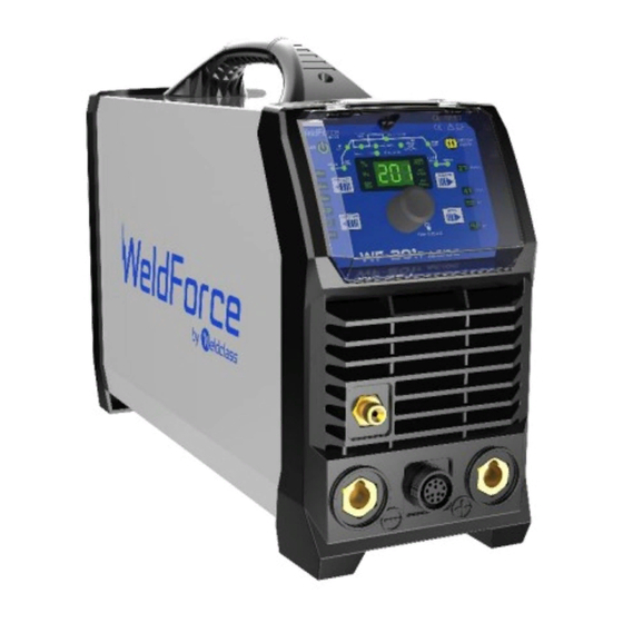
WF-201
T AC/DC
OPERATING INSTRUCTIONS
Edition 1
IMPORTANT!
To qualify for full 36 month warranty, you must register within 30 days of purchase. See inside for details.
Read these Operating Instructions Completely before attempting to use this machine. Save this manual and
keep it handy for quick reference. Pay particular attention to the safety instructions we have provided for
your protection. Contact your distributor if you do not fully understand anything in this manual.
© Weldclass 2019 | E.&O.E.
1
Advertisement
Table of Contents
Troubleshooting

Related Manuals for Weldclass WeldForce WF-201T AC/DC


Summary of Contents for Weldclass WeldForce WF-201T AC/DC
- Page 1 Read these Operating Instructions Completely before attempting to use this machine. Save this manual and keep it handy for quick reference. Pay particular attention to the safety instructions we have provided for your protection. Contact your distributor if you do not fully understand anything in this manual. © Weldclass 2019 | E.&O.E.
- Page 2 Congratulations & thank you for choosing WeldForce! The WeldForce range from Weldclass provides market leading value, features and durability. WeldForce machines have been designed with emphasis on robust construction, with simple and functional operation. Register Your Warranty Now Standard warranty without registration is 24 months.
-
Page 3: Table Of Contents
Base/Peak Current / BASE/PEAK AMP (42) ................17 4.5.8 Slope Down / DOWN SLOPE (44) .....................17 4.5.9 End Current / FINISH AMPS (45) ....................17 4.5.10 Post Flow / POST GAS (46) ....................17 4.5.11 Clean Width Area / AC BALANCE (43) ..................18 © Weldclass 2019 | E.&O.E. - Page 4 Choosing a Welding Process – MMA/Stick or TIG? ..............31 10.2.1 The Stick (MMA) Process .....................31 10.2.2 The TIG Process ........................32 10.3 Joint Preparations.........................33 STICK (MMA) BASIC WELDING GUIDE ....................35 11.1 Size of Electrodes .........................35 11.2 Storage of Electrodes ........................35 © Weldclass 2019 | E.&O.E.
- Page 5 HF Ignition ..........................48 12.3 Main Weld Current ........................49 12.3.1 DC Current..........................49 12.3.2 AC Current ..........................49 12.3.3 Pulse Welding........................50 12.3.1 AC Balance ...........................51 12.4 Finishing the Weld ........................52 12.4.1 Down-Slope ..........................52 12.4.1 Post Gas Flow ........................52 © Weldclass 2019 | E.&O.E.
- Page 6 Fire & Explosive Risks ......................60 14.4.8 Sparks & Hot Metal ......................60 14.4.9 Gas Cylinders ........................61 WARRANTY ............................62 15.1 Warranty period ...........................62 15.2 Warranty Includes and Covers......................62 15.3 Warranty Excludes / Does Not Cover ...................62 15.4 Warranty Conditions ........................63 © Weldclass 2019 | E.&O.E.
-
Page 7: Basic Specifications
110A / 24.4V @ 100% Nominal Open Circuit Voltage MMA Electrode Size 1.6 – 4.0mm Table 1 For full machine specifications, refer to technical data plate on back of machine – or go to: www.Weldclass.com.au/WF-201T © Weldclass 2019 | E.&O.E. -
Page 8: Know Your Machine
5. TIG torch Interface Connector 6. Positive (+) Welding Power Output Connection Socket Figure 1 3.2 Machine Rear 7. Mains Power Switch 8. 240V AC Mains Power Input Lead 9. Gas Inlet Connection Figure 2 © Weldclass 2019 | E.&O.E. -
Page 9: Control Panel
22. DC Arc Output Mode Indicator Light (DC) 23. Latch Trigger Mode Indicator Light (4T) 24. Trigger Mode Selection Button 25. Normal Trigger Mode Indicator Light (2T) 26. LCD Readout 27. Error/Over Temperature Indicator Light 28. Arc Parameter Chart Figure 3 © Weldclass 2019 | E.&O.E. -
Page 10: Lcd Readout
42. Base/Peak Amp Setting Indicator Light (BASE/PEAK AMP) 43. AC Arc Balance Setting Indicator Light (AC BALANCE) 44. Slope-Down Setting Indicator Light (DOWN SLOPE) 45. Finish Amps Setting Indicator Light (FINISH AMPS) 46. Post-Gas Setting Indicator Light (POST GAS) Figure 5 © Weldclass 2019 | E.&O.E. -
Page 11: Tig Torch Controls
WF-201 T AC/DC 3.6 TIG Torch Controls 47. Torch Trigger Button 48. Remote Control Amperage Potentiometer Figure 6 © Weldclass 2019 | E.&O.E. -
Page 12: Symbols Chart
Direct Current (DC) Function – Stick/MMA Negative Function Spot Weld Function Positive Pulse Function Hertz (cycles/sec) Alternating Current Duty Cycle (AC) Amperage (current) Amperage output (Current) Voltage output Voltage Table 2 AC Arc Balance 2T/Normal Trigger Function © Weldclass 2019 | E.&O.E. -
Page 13: Controls Explained
4 CONTROLS EXPLAINED 4.1 Weld Process Selection 1. Press ‘Process’ button (12) until the desired Welding Process Indicator Light (11, 13 or 14) is lit. Figure 7 4.1.1 STICK Stick/MMA welding 4.1.2 HF TIG High Frequency Start TIG welding. This uses a high frequency arc to start the welding arc which eliminates the need for the tungsten electrode to make contact with the job. -
Page 14: Output Current Mode Selection
This is also used for some specialty Stick/MMA welding. See 12.3.2 for more information. © Weldclass 2019 | E.&O.E. -
Page 15: Function Selection
Higher pulse duty setting will give greater heat input, while lower pulse duty will have the opposite effect. See 12.3.3 for more information. 4.3.3 Normal Welding Function / Off This is standard non-pulse welding mode. © Weldclass 2019 | E.&O.E. -
Page 16: Trigger Mode Selection
NOTE: The following parameter settings are only available in TIG welding modes. Figure 11 1. Press ‘Selection’ knob down (19) until the desired Arc Parameter Setting Indicator Light (36 - 46) is lit. 2. Rotate the ‘Selection’ knob to adjust the Setting © Weldclass 2019 | E.&O.E. -
Page 17: Pre-Flow Time / Pre Gas (36)
Controls the period of time the shielding gas continues to flow for after the arc is stopped. This protects the weld area and torch tungsten from contamination while it is still hot enough to react with atmospheric gases, after the weld is finished. © Weldclass 2019 | E.&O.E. -
Page 18: Clean Width Area / Ac Balance (43)
The Adjustment knob on the Foot control calibrates the maximum Base Current (as a portion of the base current set on the machine) that is represented when the Foot Pedal is right down. Foot Pedal Adjustment Knob Interface cable Figure 12 © Weldclass 2019 | E.&O.E. -
Page 19: Mma/Stick Arc Parameters/Characteristics Settings
0 is Arc Force off, 100 is maximum Arc Force. This is practically useful for electrode types that have a higher operating voltage requirement or joint types that require a short arc length such as out of position welds. © Weldclass 2019 | E.&O.E. -
Page 20: Lcd Multi-Function Display (26)
Input voltage has risen above safe Check the voltage of your power supply. tolerance level. Excessive current through IGBT Ensure usage of machine is in line with electronics due to machine misuse or guidelines in this manual. technical fault. © Weldclass 2019 | E.&O.E. - Page 21 Table 3 If you are unable to resolve the error by restarting the machine or with any of the above solutions, contact your WeldForce distributor to arrange to have the machine assessed by a technician. © Weldclass 2019 | E.&O.E.
-
Page 22: Power Supply
2. UNPLUG welder from generator BEFORE shutting generator down/turning generator off 3. NEVER let your generator run out of fuel whilst the welder is plugged in. Following these Golden Rules will significantly reduce the risk of any damage resulting from generator power supply. © Weldclass 2019 | E.&O.E. -
Page 23: Operating Environment
For further information please refer to AS 60529. Ventilation Adequate ventilation is required to provide proper cooling for the machine. Ensure that the machine is placed on a stable level surface where clean cool air can easily flow through the unit. © Weldclass 2019 | E.&O.E. -
Page 24: Basic Setup
6. Select the required output current using the Selection Knob (19). The LCD Readout (26) will display the set amperage output. 7. Adjust special Function settings if required (refer to 4.7) 8. You are now ready to weld! Figure 15 © Weldclass 2019 | E.&O.E. -
Page 25: Tig Welding Setup
18. Set the required Arc Parameters using the Selection Knob (19). (Refer to 4.5) 19. You are now ready to weld! Gas Regulator Female Gas Fitting Gas Cylinder TIG Torch Interface Connection TIG Torch Gas Connection TIG Torch (-) Earth Clamp (+) Work piece Figure 16 © Weldclass 2019 | E.&O.E. -
Page 26: Accessories, Spare Parts & Circuit Diagrams
8 ACCESSORIES, SPARE PARTS & CIRCUIT DIAGRAMS 8.1 TIG Torch and Spares: The compatible TIG torch for this machine is the Weldclass WC-06234 torch. To view this torch and parts, go to: www.weldclass.com.au Part No. Description WC-06237 Complete TIG Torch – Remote Control 200A 4m... -
Page 27: Optional Accessories
WC-04676 TIG Gloves WC-01775 Welding Gloves WC-06236 Remote Foot Control Table 5 8.3 Machine Spare Parts: For machine parts, go to www.weldclass.com.au/machines or contact your Weldclass distributor. Ref. Description Ref. Description Handle Secondary Inverter PCB Cover Fast recovery diode Switch... - Page 28 Figure 18 © Weldclass 2019 | E.&O.E.
-
Page 29: Primary Schematic Circuit Diagram
WF-201 T AC/DC 8.4 Primary Schematic Circuit Diagram Figure 19 © Weldclass 2019 | E.&O.E. -
Page 30: Care & Maintenance
Use only genuine replacement parts. Do not use modified or non-genuine parts. 9.2 Storing the Welder When not in use the welder should be stored in the dry, dust-free and frost-free environment. © Weldclass 2019 | E.&O.E. -
Page 31: General Guide To Welding
10.2.1.5 Materials MMA welding can be used with a wide variety of electrodes including general purpose, low hydrogen, stainless steel, iron powder, hard facing & cast iron just to name a few. © Weldclass 2019 | E.&O.E. -
Page 32: The Tig Process
10.2.2.5 Materials This machine incorporates AC/DC TIG function which can be used to weld a variety of materials including mild steels, stainless steels, copper and chrome moly, aluminium, titanium and zinc. © Weldclass 2019 | E.&O.E. -
Page 33: Joint Preparations
Slag should be removed from oxy-cut surfaces. Typical joint designs are shown in the following figures. Figure 24 Figure 20 Figure 25 Figure 21 Figure 26 Figure 22 Figure 27 Figure 23 Figure 28 © Weldclass 2019 | E.&O.E. - Page 34 Figure 29 © Weldclass 2019 | E.&O.E.
-
Page 35: Stick (Mma) Basic Welding Guide
Most types of cast iron, except white iron, are weldable. White iron, because of its extreme brittleness, generally cracks when attempts are made to weld it. Trouble may also be experienced when welding white-heart malleable, due to the porosity caused by gas held in this type of iron. © Weldclass 2019 | E.&O.E. -
Page 36: Types Of Electrodes
11.5.1 Mild Steel 1. General Purpose “GP” E6013 (Weldclass 12V): This all-position electrode is used for maintenance and fabrication. Works well on mild steel, galvanized steel, sheet metal, steel tube and RHS. -
Page 37: Mma Welding Techniques
Another difficulty you may meet is the tendency, after the arc is struck, to withdraw the electrode so far that the arc is broken again. A little practice will soon remedy both of these faults. Figure 30 © Weldclass 2019 | E.&O.E. -
Page 38: Arc Length
If the travel is too fast, the bead will be narrow and strung out and may even be broken up into individual globules. If the travel is too slow, the weld metal piles up and the bead will be too large. © Weldclass 2019 | E.&O.E. -
Page 39: Making Welded Joints
Plates thicker than 6.0mm should have their mating edges beveled to form a 70º to 90º included angle. This allows full penetration of the weld metal to the root. Using a 3.2mm Weldclass 12V Stick electrode at 100 amps, deposit a run of weld metal on the bottom of the joint. -
Page 40: Fillet Welds
A piece of angle iron is a suitable specimen with which to begin, or two lengths of strip steel may be tacked together at right angles. Using a 3.2mm Weldclass 12V Stick electrode at 100 amps, position angle iron with one leg horizontal and the other vertical. This is known as a horizontal-vertical (HV) fillet. -
Page 41: Vertical Welds
Tack weld a three feet length of angle iron to your work bench in an upright position. Use a 3.2mm Weldclass 12V Stick electrode and set the current at 100 amps. Make yourself comfortable on a seat in front of the job and strike the arc in the corner of the fillet. The electrode needs to be about 10º... -
Page 42: Overhead Welds
Use a 3.2mm Weldclass 12V Stick electrode at 100 amps, and deposit the first run by simply drawing the electrode along at a steady rate. You will notice that the weld deposit is rather convex, due to the effect of gravity before the metal freezes. -
Page 43: Mma (Stick) Troubleshooting
Insufficient deposit time at Pause for a moment at edge of edge of weave. weave to allow weld metal build-up. Power source is set for MIG Set power source to STICK (GMAW) welding. (MMA) mode. © Weldclass 2019 | E.&O.E. - Page 44 Redesign to relieve weld joint soon after solidification severe crack commences resistance electrodes. Insufficient throat thickness. Travel slightly slower to allow greater build up in throat. Weld current is too high. Decrease welding current. Figure 44 Table 8 © Weldclass 2019 | E.&O.E.
-
Page 45: Tig Basic Welding Guide
Filler Electrode Diameter DC Current (Amps) 1.6mm (1/16”) 60 – 115 1.6mm (1/16”) 20 – 90 2.4mm (3/32”) 100 – 165 2.4mm (3/32”) 65 – 115 3.2mm (1/8”) 135 – 200 3.2mm (1/8”) 100 – 165 Table 10 Table 11 © Weldclass 2019 | E.&O.E. -
Page 46: Preparing Tungsten
12.1.2 Preparing Tungsten The electrode should be pointed (tapered) according to the welding current. Grind end of tungsten on fine grit, hard abrasive wheel before welding. Do not use wheel for other jobs or tungsten can become contaminated causing lower weld quality. Rule of thumb is that the taper section should be 2.5 times the Electrode Diameter. -
Page 47: Shielding Gas For Tig Welding
AC Current (Amps) Argon Gas Electrode Flow Rate Unbalanced Balanced Diameter L/min Wave Wave 1.0mm (0.040”) 15-80 20-60 5 - 10 1.6mm (1/16”) 70-150 60-120 10 - 15 2.4mm (3/32”) 140-235 100-180 10 - 15 Table 15 © Weldclass 2019 | E.&O.E. -
Page 48: Starting The Weld
4. If set to 4T Trigger mode the Start Current will be maintained until you release the Torch Trigger Button and will then proceed to the Slope-Up process. If Set to 2T Trigger mode machine will proceed directly to the Slope-Up process. © Weldclass 2019 | E.&O.E. -
Page 49: Main Weld Current
AC is used for welding the following materials: Aluminium Aluminium Alloys Magnesium Zinc Figure 50 © Weldclass 2019 | E.&O.E. -
Page 50: Pulse Welding
Pulse Width percentage increase the time that is spent at the Peak Current which in turn increases the heat input into the job. Inversely reducing the Pulse Width percentage means more time is spent at the Trough Current which reduces heat input. Figure 51 © Weldclass 2019 | E.&O.E. -
Page 51: Ac Balance
The cleaner the non-ferrous metal is before welding, the more effective it is to weld. This effect can also be used to reduce heat in the tungsten, allowing use of a pointed tungsten tip shape for a more defined arc. Figure 52 Figure 53 © Weldclass 2019 | E.&O.E. -
Page 52: Finishing The Weld
12.4.1 Finish Current This gives a selected small amount of current which the operator can use to neatly complete the end of the weld. © Weldclass 2019 | E.&O.E. -
Page 53: Tig Welding Troubleshooting
Select the right shielding gas. used. Poor Work Lead/Clamp Improve connection to work piece. connection to work piece. Arc flutters during TIG welding. Tungsten electrode is too large Select the right size electrode. for the welding current. Table 16 © Weldclass 2019 | E.&O.E. -
Page 54: Knowledge & Resources
14.3 Welding Operation 1. Maintain labels and nameplates on the welder. These carry important information. If unreadable or missing, contact Weldclass for a replacement. 2. Avoid unintentional starting. Make sure the welder is setup correctly and you are prepared to begin work before turning on the welder. - Page 55 12. Do not use this machine for pipe thawing. This machine was not designed for pipe thawing and will be a significant electrical & heat hazard if attempt is made to use for thawing pipe. © Weldclass 2019 | E.&O.E.
-
Page 56: Welding Safety Instructions & Warnings
CAUTION! Have the equipment serviced by a qualified repair person using identical replacement parts. This will ensure that the safety of the power tool is maintained. © Weldclass 2019 | E.&O.E. -
Page 57: Personal Safety
5. Never wear contact lenses while welding. 14.4.3 Noise Can Damage Hearing CAUTION! Noise from some processes can damage hearing. Use AS/NZS compliant ear plugs or ear muffs if the noise level is high. © Weldclass 2019 | E.&O.E. -
Page 58: Work Environment Safety
3. Insulate yourself from the work and the ground using dry insulating mats or covers. 4. Disconnect input power before installing or servicing this equipment. Lock input power, disconnect switch open, or remove line fuses so power cannot be turned on accidentally. © Weldclass 2019 | E.&O.E. -
Page 59: Fumes And Gases
The coatings and any metals containing these elements can give off toxic fumes if welded. © Weldclass 2019 | E.&O.E. -
Page 60: Fire & Explosive Risks
WARNING! Chipping and grinding causes flying metal, and as welds cool they can throw off slag. 1. Wear an AS/NZS approved face shield or safety goggles. Side shields are recommended. 2. Wear appropriate safety equipment to protect the skin and body. © Weldclass 2019 | E.&O.E. -
Page 61: Gas Cylinders
5. Use appropriate shielding gas, regulators, hoses, and fittings designed for the specific application; maintain them and their associated parts in good condition. 6. Turn your face away from the valve outlet when opening the cylinder valve. © Weldclass 2019 | E.&O.E. -
Page 62: Warranty
7. The cost of freight, transport or travel. It is the responsibility of the purchaser to deliver the product under warranty to the nearest relevant service agent or distributor. 8. Cost for repairs carried out by a party not approved by Weldclass to carry out repairs. 9. Accessories and attachments such as leads and torches. -
Page 63: Warranty Conditions
T AC/DC 15.4 Warranty Conditions This is a repair and/or replacement warranty only and does not allow for a refund. Weldclass reserves the right to replace faulty product or parts covered under warranty with alternative / equivalent product or parts should the original unit become obsolete or unavailable. No other warranty is expressed or implied. - Page 64 © Weldclass 2019 | E.&O.E.
Need help?
Do you have a question about the WeldForce WF-201T AC/DC and is the answer not in the manual?
Questions and answers