
Related Manuals for Weldclass WeldForce WF-200MST


Summary of Contents for Weldclass WeldForce WF-200MST
- Page 1 OPERATING INSTRUCTIONS IMPORTANT! To qualify for full 24 month warranty, you must register within 30 days of purchase. See inside for details.
- Page 2 Congratulations & thank you for choosing WeldForce! The WeldForce range from Weldclass provides market leading value, features and durability. WeldForce machines have been designed with emphasis on robust construction, with simple and functional operation. Register Your Warranty Now Standard warranty without registration is 12 months. To qualify for an extended full 24 month warranty your purchase you must register within 30 days of purchase.
-
Page 3: Table Of Contents
Contents Know Your Machine ....................5 Controls Explained ....................5 Power Supply ....................... 6 Operating Environment ..................6 Welding Settings ...................... 10 Tips & Tricks ....................... 10 Accessories & Spare Parts: ................11 Care & Maintenance .................... 12 MIG Basic Welding Guide ................ - Page 4 1.6 – 4.0mm TIG Tungsten Size 1.6 – 2.4mm Spool Size 200mm (4.5kg or 5kg) & 300mm (15kg) Input Power 240V, 15A For full machine specifications, refer to technical data plate on back of machine – or go to: www.Weldclass.com.au/WF-200MST...
-
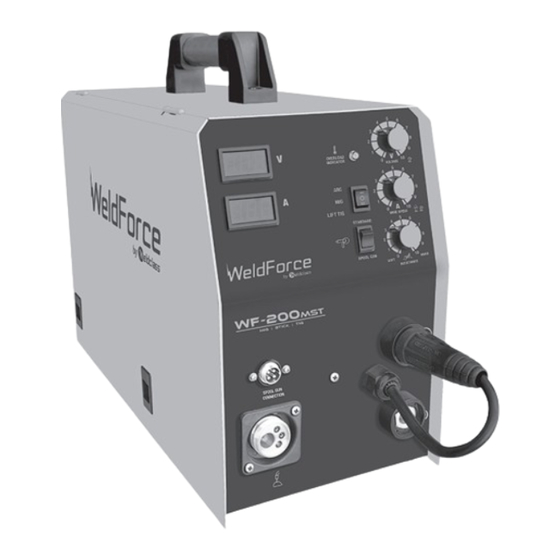
Page 5: Know Your Machine
Know Your Machine MIG Torch Euro Connection Spool Gun Connection Socket Spool Gun Switch LCD Current Meter - Displays output current (amps) in real time* 5. LCD Voltage Meter - Displays output voltage in real time* Welding Output Mode Switch - Sets power source in MIG, MMA or Lift TIG mode* Overload Indicator Lamp*... -
Page 6: Power Supply
MIG Voltage & MIG Wire Speed / MMA Lift TIG Mode & Lift TIG Current Control Knobs Lift TIG is an arc ignition system for basic TIG welding that removes the need to ‘scratch’ start or strike the MIG Welding Mode tungsten on the work piece to start the arc, which can have a negative effect on the weld quality due The MIG voltage control is essentially the power in... - Page 7 Basic Operation - MIG Welding necessary, remove and change the drive roller by unthreading the drive roller retainer (22). 1. Fitting Wire Spool Once the correct drive roller (23) is selected and fitted and the drive roller retainer (22) 1.1 Open the wire feeder compartment door. is secured in place, manually feed the wire Remove the wire spool holder (18) by through the wire drive inlet guide (19),...
- Page 8 2.8 You are now ready to feed the wire through connections are tight. Open gas cylinder valve the torch. With the wire feeder cover open, and adjust regulator, flow should be between pull the trigger of the MIG torch to check that 10-25L/min depending on application.
- Page 9 6. ARC/ MMA Welding Operation reduces the wire feeding friction and improves the wire feed speed smoothness and consistency, 6.1 Connect the earth cable quick connector to thus the welding quality is greatly improved. This the negative welding power output socket is especially so with ‘soft’...
-
Page 10: Welding Settings
Tips & Tricks up the machine. Set the welding mode switch (6) to ‘Lift TIG’ . Duty Cycle Rating 7.5 Select the required output current using the current control knob (9). You are now ready to Welding duty cycle is the percentage of actual weld! welding time that can occur in a ten minute cycle. -
Page 11: Accessories & Spare Parts
The MIG Torch supplied with the WF-200MST is a BZL 25 (Binzel 25 style) model. To view parts for this torch, go to: www.weldclass.com.au/BZL25parts TIG Torch (Optional Extra): The compatible TIG torch for this machine is Weldclass 9/17 torch with valve. To view this torch, go to: www.weldclass.com.au/TigTorch917v Machine Spare Parts: For machine parts, go to www.weldclass.com.au/machines or contact... -
Page 12: Care & Maintenance
Care & Maintenance Storing the Welder When not in use the welder should be stored in the Keep your Welding Machine in Top dry and frost-free environment. Condition The WF-200MST does not require any special WARNING! maintenance, however the user should take care Before performing cleaning/maintenance,... - Page 13 Gas Metal Arc Welding (GMAW) Position of MIG Torch (Fig 1-3) This process, also known as MIG welding, CO2 welding, Micro Wire Welding, short arc welding, dip transfer welding, wire welding etc., is an electric arc welding process which fuses together the parts to be welded by heating them with an arc between a solid continuous, consumable electrode and the work.
- Page 14 Primary Adjustable Variables Vertical Fillet Welds (Fig 1-6) to 20 Longitudinal Angle These control the process after preselected variables have been found. They control the Longitudinal Angle penetration, bead width, bead height, arc stability, deposition rate and weld soundness. to 60 These variables are: to 60 Transverse...
- Page 15 Whether the operator is left handed or right handed has to be considered to realize the effects of each angle in relation to the direction of travel. Nozzle Angle, Right Handed Operator (Fig 1-10) Direction of Travel Leading or “Pushing” Trailing or “Pulling”...
-
Page 16: Mig Welding Troubleshooting
MIG Welding When there is a gas problem the result is usually porosity within the weld metal. Porosity always Troubleshooting stems from some contaminant within the molten weld pool which is in the process of escaping during solidification of the molten metal. The general approach to fix Gas Metal Arc Welding (GMAW) problems is to start at the wire spool then Contaminants range from no gas around the... - Page 17 Wire feeding problems can be reduced by checking the following points. (Replace liner) (Replace liner) Other weld problems can be reduced by checking the following points.
-
Page 18: Mma (Stick) Basic Welding Guide
MMA (Stick) Basic Flat Position, Down Hand Butt Weld Welding Guide (Fig 1-11) Size of Electrodes The electrode size is determined by the thickness Flat Position, of metals being joined and can also be governed Gravity Fillet Weld by the type of welding machine available. Small (Fig 1-12) welding machines will only provide current (amperage) to run smaller sized electrodes. - Page 19 brittleness, generally cracks when attempts are between the pieces being joined to ensure proper made to weld it. Trouble may also be experienced penetration of the weld metal and to produce when welding white-heart malleable, due to the sound joints. In general, surfaces being welded porosity caused by gas held in this type of iron.
- Page 20 MMA Welding Techniques Corner Weld - A Word for Beginners (Fig 1-19g) For those who have not yet done any welding, the simplest way to commence is to run beads on a piece of scrap plate. Use mild steel plate about 6.0mm thick and a 3.2mm electrode.
- Page 21 Making Welded Joints the electrode slowly along as it melts down. Having attained some skill in the handling of an Another difficulty you may meet is the tendency, electrode, you will be ready to go on to make up after the arc is struck, to withdraw the electrode so welded joints.
- Page 22 Heavy plate will require several runs to complete the joint. After completing the first run, chip the Multi-Runs in HV Fillet Weld (Fig 1-24) slag out and clean the weld with a wire brush. It is important to do this to prevent slag being trapped by the second run.
- Page 23 iron at right angles to another piece of waste pipe. Examples of Vertical Fillet Welds Then tack this to the work bench or hold in a vice (Fig 1-27) so that the specimen is positioned in the overhead CORRECT INCORRECT position as shown in the sketch.
-
Page 24: Mma (Stick) Troubleshooting
MMA (Stick) Troubleshooting... -
Page 25: Tig Basic Welding Guide
TIG Basic Welding Guide TIG Welding is a fusion procedure that uses an electric ARC created between an infusible tungsten electrode and base material to be welded. For TIG welding an inert gas must be used (Argon) which protects the welding bead. If filling material is used, it is made up of rods suitable to the material to be welded (steel, stainless steel, copper etc). - Page 26 (Fig 16-3) ARC Welder Point Grinding Wheel Radial Ground Wrong Tungsten Preparation - Wandering ARC Diameter of the flat determines amperage capacity. (Fig 17) Pointing the Electrode The electrode should be pointed according to the welding current.
-
Page 27: Tig Welding Troubleshooting
TIG Welding Troubleshooting... -
Page 28: Knowledge & Resources
MIG Welding Operation 1. Maintain labels and nameplates on the Resources welder. These carry important information. If unreadable or missing, contact Weldclass for a Please refer to Weldclass website replacement. www.weldclass.com.au for more information. 2. Avoid unintentional starting. Make sure the... - Page 29 10. Transportation Methods. Lift unit with DANGER! the handles provided, or use a handcart or Always wear AS/NZS compliant safety glasses similar device of adequate capacity. If using a and full face shield fitted with appropriate filter fork lift vehicle, secure the unit to a skid before shade number.
- Page 30 Use protective screens or barriers to protect Do not apply heat to a container that has others from flash and glare; warn others not to held an unknown substance or a combustible watch the arc. material whose contents, when heated, can produce flammable or explosive vapours.
- Page 31 11. Do not touch the electrode while in contact Use a Welding Helmet or Welding Face Shield with the work (ground) circuit. fitted with a proper shade of filter (see AS 60974-1, AS/NZS 1337.1 and AS/NZS 1338.1 12. Use only well-maintained equipment. Repair Safety Standards) to protect your face and or replace damaged parts as soon as practical.
- Page 32 If ventilation is poor, use an approved air- Connect the work lead/clamp to the job supplied respirator. as close to the welding area as practical to prevent welding current from traveling long, Read the Safety Data Sheets (SDS) and the possibly unknown paths and causing electric manufacturer’s instruction for the metals, shock and fire hazards.
-
Page 33: Warranty
8. Cost for repairs carried out by a party not approved by Weldclass to carry out repairs. 9. Accessories and attachments such as leads and torches. - Page 36 www.Weldclass.com.au/WF-200MST...
Need help?
Do you have a question about the WeldForce WF-200MST and is the answer not in the manual?
Questions and answers
location of fuse