Table of Contents
Advertisement
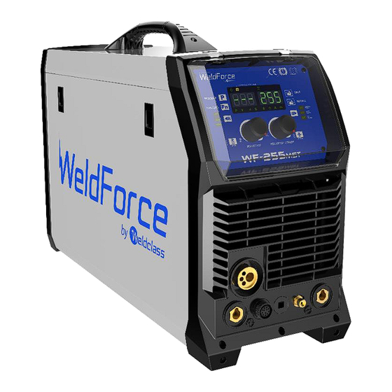
WF-255
MST
OPERATING INSTRUCTIONS
Edition 2.2
IMPORTANT!
To qualify for full 36 month warranty, you must register within 30 days of purchase. See inside for details.
Read these Operating Instructions Completely before attempting to use this machine. Save this manual and
keep it handy for quick reference. Pay particular attention to the safety instructions we have provided for
your protection. Contact your distributor if you do not fully understand anything in this manual.
© Weldclass 2019 | E.&O.E. | Edition 2.2
1
Advertisement
Table of Contents
Troubleshooting

Related Manuals for Weldclass WeldForce WF-255MST


Summary of Contents for Weldclass WeldForce WF-255MST
- Page 1 Pay particular attention to the safety instructions we have provided for your protection. Contact your distributor if you do not fully understand anything in this manual. © Weldclass 2019 | E.&O.E. | Edition 2.2...
- Page 2 Congratulations & thank you for choosing WeldForce! The WeldForce range from Weldclass provides market leading value, features and durability. WeldForce machines have been designed with emphasis on robust construction, with simple and functional operation. Register Your Warranty Now Standard warranty without registration is 24 months.
-
Page 3: Table Of Contents
4T (Latch Trigger) ........................19 4.4.3 SP (Spot/Stitch) ........................19 Inductance Control ........................20 Test Gas ............................20 Feed Wire / Wire Inch ........................21 Job Memory ..........................21 4.8.1 Save or Update a Job ........................21 4.8.2 Recall a Job ..........................22 © Weldclass 2019 | E.&O.E. | Edition 2.2... - Page 4 Keep your Welding Machine in Top Condition ................41 Storing the Welder ........................41 GENERAL GUIDE TO WELDING ......................42 10.1 Duty Cycle Rating .........................42 10.2 Choosing a Welding Process – MIG, Stick or TIG? ................42 © Weldclass 2019 | E.&O.E. | Edition 2.2...
- Page 5 12.4.1 High Tensile and Alloy Steels ....................56 12.4.2 Manganese Steels ........................56 12.4.3 Cast Iron ..........................56 12.5 Types of Electrodes ........................57 12.5.1 MILD STEEL: .........................57 12.5.2 CAST IRON: ...........................57 12.5.3 STAINLESS STEEL: .........................57 © Weldclass 2019 | E.&O.E. | Edition 2.2...
- Page 6 Fire & Explosive Risks ......................76 15.4.8 Sparks & Hot Metal ......................76 15.4.9 Gas Cylinders ........................77 WARRANTY ............................78 16.1 Warranty period ...........................78 16.2 Warranty Includes and Covers......................78 16.3 Warranty Excludes / Does Not Cover ...................78 © Weldclass 2019 | E.&O.E. | Edition 2.2...
- Page 7 WF-255 16.4 Warranty Conditions ........................79 © Weldclass 2019 | E.&O.E. | Edition 2.2...
-
Page 8: Basic Specifications
200mm (5kg) & 300mm (15kg) MIG Wire Sizes 0.6, 0.8, 0.9, 1.0, 1.2mm Stick (MMA) Welding MMA Electrode Size 1.6 – 4.0mm TIG Welding TIG Tungsten Size 1.6 – 2.4mm Table 1 © Weldclass 2019 | E.&O.E. | Edition 2.2... - Page 9 195A / 17.8V @ 60% 150A / 16.0V @ 100% Nominal Open Circuit Voltage Table 3 For full machine specifications, refer to technical data plate on back of machine – or go to: www.Weldclass.com.au/WF-255MST © Weldclass 2019 | E.&O.E. | Edition 2.2...
-
Page 10: Know Your Machine
17. Centre Wire Guide Tube 18. Right Drive Roller Retainer Knob 19. Right Drive Roller 20. Outlet Wire Guide Tube 21. Right Wire Feed Tension Arm/Top Roller 22. Right Wire Feed Tension Adjustment Lever Figure 2 © Weldclass 2019 | E.&O.E. | Edition 2.2... -
Page 11: Machine Rear
33. Wire Feed/Load Button (Feed Wire) 34. Trigger Mode Selection Button (Trigger) 35. Trigger Mode Indicator Lights 36. Job Recall Button 37. Job Save Button 38. Right LCD Readout 39. Left LCD Readout Figure 4 © Weldclass 2019 | E.&O.E. | Edition 2.2... -
Page 12: Lcd Readout
46. Seconds Setting Indicator Light 47. Wire Speed Setting Indicator Light 48. Material Thickness Setting Indicator Light 49. Amperage Setting Indicator Light 50. Job Save/Recall Selection Indicator Light 51. VRD Indicator Light Figure 5 © Weldclass 2019 | E.&O.E. | Edition 2.2... -
Page 13: Symbols Chart
TIG Function Direct Current (DC) – Stick/MMA Negative Function Material Thickness Positive Wire Feed Hertz (cycles/sec) Amperage (current) Duty Cycle output Amperage Voltage output (Current) Variable Voltage Inductance Table 4 Increase/Decrease Save Settings © Weldclass 2019 | E.&O.E. | Edition 2.2... -
Page 14: Controls Explained
4.1 Weld Process Selection 1. Press ‘Process’ button (29) until the desired Welding Process Indicator Light (28) is lit. Figure 6 4.1.1 MIG Process: In Manual MIG mode (Program 0) – before welding the Left Selection Knob (31) adjusts target voltage output and the Right Selection Knob (32) adjusts Target Wire Speed (m/min). -
Page 15: Mig Program Selection
0.9mm Flux Cored Steel Gasless or Gas 1.0mm 1.2mm 0.8mm 0.9mm Stainless Steel Mixed or Argon 1.0mm 1.2mm 0.8mm Silicone Bronze (CuSi) Argon 0.9mm 0.8mm 0.9mm Aluminium Argon 1.0mm 1.2mm Table 5 © Weldclass 2019 | E.&O.E. | Edition 2.2... -
Page 16: Function Selection
Spot/Stitch Weld Time (sec) Stitch Weld Gap/Interval Time (sec) Spool Gun (On/Off) TIG MODE Post-Gas Time (sec) Slope Up Time (sec) STICK (MMA) MODE Hot Start Adjustment Arc Force Adjustment Table 6 © Weldclass 2019 | E.&O.E. | Edition 2.2... -
Page 17: Pre-Gas Time (Mig)
TIP! If you are only doing individual ‘Spot’ welds (single welds, no repeat) it is suggested to set this Stitch Weld Gap time to maximum and release the trigger before the weld repeats. © Weldclass 2019 | E.&O.E. | Edition 2.2... -
Page 18: Spool Gun On/Off (Mig)
The VRD function will turn on full welding power/voltage when the resistance between the electrode and work piece is less than 200 Ohms (i.e. metal to metal contact). When the VRD function is active, the VRD Active Indicator Light (51) is illuminated. Figure 9 © Weldclass 2019 | E.&O.E. | Edition 2.2... -
Page 19: Trigger Mode Selection
Spot Welding trigger mode is used for Spot, Tacking or Stitch welding. It allows you to set fixed times for welding time and interval between welding and automatically repeats this process until the trigger is released. © Weldclass 2019 | E.&O.E. | Edition 2.2... -
Page 20: Inductance Control
The ‘Test Gas’ button (30) works in both MIG and TIG process modes. This simply opens gas flow (without feeding wire or giving arc voltage) to allow user to check that there is sufficient gas flow coming out of the torch nozzle. Figure 12 © Weldclass 2019 | E.&O.E. | Edition 2.2... -
Page 21: Feed Wire / Wire Inch
5. Write a brief description beside the Job Number on the ‘Job Number Register’ chart on the inside of the door of the machine so you know what number was allocated to that job. 3mm Cattle Rail 2, 4 Figure 14 © Weldclass 2019 | E.&O.E. | Edition 2.2... -
Page 22: Recall A Job
When thermal protection is activated, welding output will be disabled until machines cools sufficiently and overload indicator lamp goes out. This may also activate if there are electronic circuit failure issues. Figure 16 © Weldclass 2019 | E.&O.E. | Edition 2.2... -
Page 23: Power Supply
Table 2 are not exceeded. If using 25A power supply, extension lead should be minimum cable core size 4.0mm Using extension leads of over 100m is not recommended. © Weldclass 2019 | E.&O.E. | Edition 2.2... -
Page 24: Generator Use
3. NEVER let your generator run out of fuel whilst the welder is plugged in. Following these Golden Rules will significantly reduce the risk of any damage resulting from generator power supply. © Weldclass 2019 | E.&O.E. | Edition 2.2... -
Page 25: Operating Environment
Adequate ventilation is required to provide proper cooling for the machine. Ensure that the machine is placed on a stable level surface where clean cool air can easily flow through the unit. © Weldclass 2019 | E.&O.E. | Edition 2.2... -
Page 26: Basic Operation
5. Replace the Spool Nut (10) by threading it back on the Spool Post (9). 6. Feed the wire from the spool through the Wire Inlet Guide (12) into the wire feeder. Spool Tension Bolt Spool Post Spool nut Wire Inlet Guide Figure 17 © Weldclass 2019 | E.&O.E. | Edition 2.2... -
Page 27: Fitting Wire Spool - 200Mm Diameter (5Kg)
Spool Post before you fit the Wire Spool. Take care to ensure that the Spool Lock Pins are aligned. 200mm Spool Spacer Spool Post Spool nut 200mm Wire Spool Figure 18 © Weldclass 2019 | E.&O.E. | Edition 2.2... -
Page 28: Loading Wire Feeder
11. Press the ‘Feed Wire’ button (33) until the wire feeds out through the end of the MIG torch. 12. Replace the tip on the MIG torch and trim off any excess wire. © Weldclass 2019 | E.&O.E. | Edition 2.2... -
Page 29: Gasless Welding Setup
3. Connect the MIG Torch Polarity Change Tail (8) to the Negative (-) Output Connection (7). Note: if this connection is not made, there will be no electrical connection to the welding torch! Figure 20 © Weldclass 2019 | E.&O.E. | Edition 2.2... -
Page 30: Gas Mig Welding Setup
5. Open gas cylinder valve and adjust regulator. Press ‘Test Gas’ button (30) to initiate flow of gas through the welding torch. Flow should be between 10-25L/min depending on application. Figure 21 © Weldclass 2019 | E.&O.E. | Edition 2.2... -
Page 31: Additional Setup For Mig Welding With Aluminium
2. Replace the liner in the MIG Torch with a special Graphite/Teflon/PVC liner (rather than the conventional steel liner). The Weldclass Universal Graphite liner kit is recommended (P3-CTUL09) 3. Choose the largest dimeter wire possible that can but used by your machine for your application. -
Page 32: Adjusting Settings For Mig Welding In Manual Mode (Program 0)
5. You can use the Left Adjustment Knob (31) to fine tune the voltage if the standard synergic program does not suit your exact welding application. 6. Adjust Inductance if required (refer to 4.5) 7. Adjust special Function settings if required (refer to 4.3) © Weldclass 2019 | E.&O.E. | Edition 2.2... -
Page 33: Stick (Mma) Welding Operation
6. Select the required output current using the Right Adjustment Knob (32). The Right LCD Readout (38) will display the set amperage output. 7. Adjust special Function settings if required (refer to 4.3) 8. You are now ready to weld! Figure 22 © Weldclass 2019 | E.&O.E. | Edition 2.2... -
Page 34: Lift Tig Operation
9. Select the required output current using the Right Adjustment Knob (32). The Right LCD Digital Readout (38) will display the set amperage output. 10. Adjust special Function settings if required (refer to 4.3) 11. You are now ready to weld! Figure 23 © Weldclass 2019 | E.&O.E. | Edition 2.2... -
Page 35: Accessories, Spare Parts & Circuit Diagrams
Tip 1.0mm Pk5 P3-BT612 Tip 1.2mm Pk5 P3-BTA610 Tip 1.0mm Alu Pk5 P3-BTA612 Tip 1.2mm Alu/Flux Core Pk5 P3-B25N Nozzle Pk2 P3-BRSL4 Liner – Steel wires P3-CTUL12 Liner – Aluminium wire Table 7 © Weldclass 2019 | E.&O.E. | Edition 2.2... -
Page 36: Tig Torch And Spares (Optional Extra)
8.2 TIG Torch and Spares (Optional Extra): The compatible TIG torch for this machine is the Weldclass WC-06234 torch. To view this torch and parts, go to: www.weldclass.com.au Part No. Description WC-06234 Complete TIG Torch – Remote Control 150A 4m... -
Page 37: Optional Accessories
0.6 / 0.8mm V-Groove (Steel) WC-06192 0.9 / 1.2mm V-Groove (Steel) WC-06193 0.8 / 0.9mm Knurled (Flux Cored) WC-06194 0.9 / 1.2mm Knurled (Flux Cored) WC-06195 1.0 / 1.2mm U-Groove (Aluminium) Table 10 © Weldclass 2019 | E.&O.E. | Edition 2.2... -
Page 38: Machine Spare Parts
Wire connector Insulation part Euro socket Recovery diode 9 Pin socket Insulation part Power cable clip IGBT Gas fitting Heatsink Central socket Thermistor Gas fitting Heatsink Connector Heatsink Table 11 Recovery Diode © Weldclass 2019 | E.&O.E. | Edition 2.2... - Page 39 WF-255 Figure 25 © Weldclass 2019 | E.&O.E. | Edition 2.2...
-
Page 40: Primary Schematic Circuit Diagram
8.6 Primary Schematic Circuit Diagram Figure 26 © Weldclass 2019 | E.&O.E. | Edition 2.2... -
Page 41: Care & Maintenance
Use only genuine replacement parts. Do not use modified or non-genuine parts. 9.2 Storing the Welder When not in use the welder should be stored in the dry, dust-free and frost-free environment. © Weldclass 2019 | E.&O.E. | Edition 2.2... -
Page 42: General Guide To Welding
10.2.1.5 Materials MMA welding can be used with a wide variety of electrodes including general purpose, low hydrogen, stainless steel, iron powder, hard facing & cast iron just to name a few. © Weldclass 2019 | E.&O.E. | Edition 2.2... -
Page 43: The Tig Process
It does not rely on the operator to feed in filler wire like TIG welding. Also because the filler wire is on a roll it lasts significantly longer than a Stick welding electrode so © Weldclass 2019 | E.&O.E. | Edition 2.2... -
Page 44: Joint Preparations
Slag should be removed from oxy-cut surfaces. Typical joint designs are shown in the following figures. Figure 27 Figure 30 Figure 31 Figure 28 Figure 32 Figure 29 © Weldclass 2019 | E.&O.E. | Edition 2.2... - Page 45 WF-255 Figure 33 Figure 34 Figure 36 Figure 35 © Weldclass 2019 | E.&O.E. | Edition 2.2...
-
Page 46: Mig Basic Welding Guide
It is commonly used to weld large diameter wires in the flat and horizontal position and small wire diameters in all positions. The process is used to a lesser degree for welding stainless steel and for overlay work. Figure 38 © Weldclass 2019 | E.&O.E. | Edition 2.2... -
Page 47: Position Of Mig Torch
Generally solid wire is about 10mm and flux-cored/gasless wire about 15-20mm. 11.6 Travel Speed The speed at which the molten pool travels influences the width of the weld and penetration of the welding run. © Weldclass 2019 | E.&O.E. | Edition 2.2... -
Page 48: Mig Welding (Gmaw) Variables
Maintain at about 10mm stick-out for solid wire and 15-20mm for gasless wire. Figure 40 2. Wire Feed Speed: Increase in wire feed speed increases weld current/amperage. Decrease in wire feed speed decreases weld current. © Weldclass 2019 | E.&O.E. | Edition 2.2... - Page 49 Figure 42 Figure 41 Horizontal Butt Weld Vertical Fillet Welds Figure 43 Figure 45 Horizontal Fillet Weld Overhead Fillet Weld Figure 46 Figure 44 © Weldclass 2019 | E.&O.E. | Edition 2.2...
-
Page 50: Establishing The Arc And Making Weld Beads
11.8 Establishing the Arc and Making Weld Beads Before attempting to weld on a finished piece of work, it is recommended that practice welds be made on a sample metal of the same material as that of the finished piece. The easiest welding procedure for the beginner to experiment with MIG welding is the flat position. -
Page 51: How To Determine Correct Wire Speed/Voltage Setting
4. The amount of penetration required 5. The deposition rate required 6. The bead profile desired 7. The position of welding 8. Cost of the wire 9. Environment (can shielding gas be used or not?) © Weldclass 2019 | E.&O.E. | Edition 2.2... -
Page 52: Mig Welding Troubleshooting
Check that the MIG torch O-rings are not damaged on the Euro connector. Table 13 WARNING! Disengage the feed roll when testing for gas flow by ear or use the ‘Gas Test’ button © Weldclass 2019 | E.&O.E. | Edition 2.2... -
Page 53: Wire Feed Problems
Bent liner (Replace liner) This will cause friction between the wire and the liner this reducing wire feed. Table 15 © Weldclass 2019 | E.&O.E. | Edition 2.2... -
Page 54: Weld Quality Problems
Figure 52 Excessive weld stresses. Increase weld metal strength or revise design. Excessive voltage. Decrease voltage. Cooling rate too fast. Slow the cooling rate by preheating part to be welded or cool slowly. © Weldclass 2019 | E.&O.E. | Edition 2.2... - Page 55 (-) speed and voltage are welding terminal for gasless adjusted correctly wires. Refer to the wire manufacturer for the correct polarity. Table 16 © Weldclass 2019 | E.&O.E. | Edition 2.2...
-
Page 56: Stick (Mma) Basic Welding Guide
Most types of cast iron, except white iron, are weldable. White iron, because of its extreme brittleness, generally cracks when attempts are made to weld it. Trouble may also be experienced when welding white-heart malleable, due to the porosity caused by gas held in this type of iron. © Weldclass 2019 | E.&O.E. | Edition 2.2... -
Page 57: Types Of Electrodes
12.5.1 MILD STEEL: 1. General Purpose “GP” E6013 (Weldclass 12V): This all-position electrode is used for maintenance and fabrication. Works well on mild steel, galvanized steel, sheet metal, steel tube and RHS. -
Page 58: Mma Welding Techniques
Another difficulty you may meet is the tendency, after the arc is struck, to withdraw the electrode so far that the arc is broken again. A little practice will soon remedy both of these faults. Figure 53 © Weldclass 2019 | E.&O.E. | Edition 2.2... -
Page 59: Arc Length
If the travel is too fast, the bead will be narrow and strung out and may even be broken up into individual globules. If the travel is too slow, the weld metal piles up and the bead will be too large. © Weldclass 2019 | E.&O.E. | Edition 2.2... -
Page 60: Making Welded Joints
Plates thicker than 6.0mm should have their mating edges beveled to form a 70º to 90º included angle. This allows full penetration of the weld metal to the root. Using a 3.2mm Weldclass 12V Stick electrode at 100 amps, deposit a run of weld metal on the bottom of the joint. -
Page 61: Fillet Welds
A piece of angle iron is a suitable specimen with which to begin, or two lengths of strip steel may be tacked together at right angles. Using a 3.2mm Weldclass 12V Stick electrode at 100 amps, position angle iron with one leg horizontal and the other vertical. This is known as a horizontal-vertical (HV) fillet. -
Page 62: Vertical Welds
Tack weld a three feet length of angle iron to your work bench in an upright position. Use a 3.2mm Weldclass 12V Stick electrode and set the current at 100 amps. Make yourself comfortable on a seat in front of the job and strike the arc in the corner of the fillet. The electrode needs to be about 10º... -
Page 63: Overhead Welds
Use a 3.2mm Weldclass 12V Stick electrode at 100 amps, and deposit the first run by simply drawing the electrode along at a steady rate. You will notice that the weld deposit is rather convex, due to the effect of gravity before the metal freezes. -
Page 64: Mma (Stick) Troubleshooting
Insufficient deposit time at Pause for a moment at edge of edge of weave. weave to allow weld metal build-up. Power source is set for MIG Set power source to STICK (GMAW) welding. (MMA) mode. © Weldclass 2019 | E.&O.E. | Edition 2.2... - Page 65 Insufficient throat thickness. Travel slightly slower to allow greater build up in throat. Weld current is too high. Decrease welding current. Figure 67 Table 18 © Weldclass 2019 | E.&O.E. | Edition 2.2...
-
Page 66: Tig Basic Welding Guide
Table 19 * Note that the WeldForce WF-255MST machine is only capable of DC TIG welding. It cannot perform AC TIG welding required to weld Aluminium. Tungsten Electrode Current Ranges... -
Page 67: Preparing Tungsten For Dc Electrode Negative (Dcen) Welding
13.1.2 Preparing Tungsten for DC Electrode Negative (DCEN) Welding The electrode should be pointed (tapered) according to the welding current. Grind end of tungsten on fine grit, hard abrasive wheel before welding. Do not use wheel for other jobs or tungsten can become contaminated causing lower weld quality. Rule of thumb is that the taper section should be 2.5 times the Electrode Diameter. -
Page 68: Shielding Gas For Tig Welding
40-60 1.6mm 1.6mm Butt/ Corner 10-15 (1/16”) (1/16”) (1/16”) 70-90 50-70 Lap / Fillet 80-100 65-85 Butt/ Corner 3.2mm 1.6mm 2.4mm 10-15 (1/8”) 90-115 90-110 (1/16”) (3/32”) Lap / Fillet Table 24 © Weldclass 2019 | E.&O.E. | Edition 2.2... -
Page 69: Tig Welding Troubleshooting
Work Lead/Clamp Improve connection to work piece. connection to work piece. Arc flutters during TIG welding. Tungsten electrode is too large Select the right size electrode. for the welding current. Table 25 © Weldclass 2019 | E.&O.E. | Edition 2.2... -
Page 70: Knowledge & Resources
15.3 Welding Operation 1. Maintain labels and nameplates on the welder. These carry important information. If unreadable or missing, contact Weldclass for a replacement. 2. Avoid unintentional starting. Make sure the welder is setup correctly and you are prepared to begin work before turning on the welder. - Page 71 12. Do not use this machine for pipe thawing. This machine was not designed for pipe thawing and will be a significant electrical & heat hazard if attempt is made to use for thawing pipe. © Weldclass 2019 | E.&O.E. | Edition 2.2...
-
Page 72: Welding Safety Instructions & Warnings
CAUTION! Have the equipment serviced by a qualified repair person using identical replacement parts. This will ensure that the safety of the power tool is maintained. © Weldclass 2019 | E.&O.E. | Edition 2.2... -
Page 73: Personal Safety
5. Never wear contact lenses while welding. 15.4.3 Noise Can Damage Hearing CAUTION! Noise from some processes can damage hearing. Use AS/NZS compliant ear plugs or ear muffs if the noise level is high. © Weldclass 2019 | E.&O.E. | Edition 2.2... -
Page 74: Work Environment Safety
3. Insulate yourself from the work and the ground using dry insulating mats or covers. 4. Disconnect input power before installing or servicing this equipment. Lock input power, disconnect switch open, or remove line fuses so power cannot be turned on accidentally. © Weldclass 2019 | E.&O.E. | Edition 2.2... -
Page 75: Fumes And Gases
2. If inside, ventilate the area and/or use an exhaust at the arc to remove welding fumes and gases. 3. If ventilation is poor, use an approved supplied-air respirator (PAPR). 4. Read the Safety Data Sheets (SDS) and the manufacturer’s instruction for the metals, consumables, coatings, and cleaners. © Weldclass 2019 | E.&O.E. | Edition 2.2... -
Page 76: Fire & Explosive Risks
WARNING! Chipping and grinding causes flying metal, and as welds cool they can throw off slag. 1. Wear an AS/NZS approved face shield or safety goggles. Side shields are recommended. 2. Wear appropriate safety equipment to protect the skin and body. © Weldclass 2019 | E.&O.E. | Edition 2.2... -
Page 77: Gas Cylinders
5. Use appropriate shielding gas, regulators, hoses, and fittings designed for the specific application; maintain them and their associated parts in good condition. 6. Turn your face away from the valve outlet when opening the cylinder valve. © Weldclass 2019 | E.&O.E. | Edition 2.2... -
Page 78: Warranty
7. The cost of freight, transport or travel. It is the responsibility of the purchaser to deliver the product under warranty to the nearest relevant service agent or distributor. 8. Cost for repairs carried out by a party not approved by Weldclass to carry out repairs. 9. Accessories and attachments such as leads and torches. - Page 79 WF-255 16.4 Warranty Conditions This is a repair and/or replacement warranty only and does not allow for a refund. Weldclass reserves the right to replace faulty product or parts covered under warranty with alternative / equivalent product or parts should the original unit become obsolete or unavailable. No other warranty is expressed or implied.
- Page 80 © Weldclass 2019 | E.&O.E. | Edition 2.2...
Need help?
Do you have a question about the WeldForce WF-255MST and is the answer not in the manual?
Questions and answers