Table of Contents
Advertisement
Quick Links
Weldforce 202
T AC/DC
Weldforce 202T
HF Pulse AC/DC TIG
OPERATING INSTRUCTIONS
Edition 1.6
IMPORTANT!
To qualify for full 24 month warranty, you must register within 30 days of purchase. See inside for details.
Read these Operating Instructions Completely before attempting to use this machine. Save this manual and
keep it handy for quick reference. Pay particular attention to the safety instructions we have provided for
your protection. Contact your distributor if you do not fully understand anything in this manual.
© Weldclass 2020 | E.&O.E.
1
Advertisement
Table of Contents
Troubleshooting

Related Manuals for Weldclass Weldforce 202T


Summary of Contents for Weldclass Weldforce 202T
- Page 1 Read these Operating Instructions Completely before attempting to use this machine. Save this manual and keep it handy for quick reference. Pay particular attention to the safety instructions we have provided for your protection. Contact your distributor if you do not fully understand anything in this manual. © Weldclass 2020 | E.&O.E.
- Page 2 Congratulations & thank you for choosing Weldclass! The Weldforce range from Weldclass provides market leading value, features and durability. Register Your Warranty Now To qualify for an extended warranty, you must register within 30 days of purchase. Full details on warranty period and terms can be found at www.weldclass.com.au/WarrantyInfo...
-
Page 3: Table Of Contents
Main Amps (7d) ........................16 4.5.5 Base Amps (7e).........................17 4.5.6 Frequency (7f) ..........................17 4.5.1 Balance (7g) ..........................17 4.5.1 Spot Time (7h) ..........................18 4.5.2 Slope Down (7k) ........................18 4.5.3 Finish Amps (7l) ........................18 4.5.4 Post-Gas Time (7m) ........................18 © Weldclass 2020 | E.&O.E. - Page 4 GENERAL GUIDE TO WELDING ......................31 10.1 Duty Cycle Rating .........................31 10.2 Choosing a Welding Process – MMA/Stick or TIG? ..............31 10.2.1 The Stick (MMA) Process .....................31 10.2.2 The TIG Process ........................32 10.3 Joint Preparations ........................33 © Weldclass 2020 | E.&O.E.
- Page 5 Typical TIG Welding Settings ....................47 12.2 Starting the Weld .........................48 12.2.1 Lift-Arc Ignition........................48 12.2.2 HF Ignition ..........................48 12.3 Main Weld Current ........................49 12.3.1 DC Current ...........................49 12.3.2 AC Current ..........................49 12.3.3 Pulse Welding........................50 12.3.4 AC Balance ...........................51 © Weldclass 2020 | E.&O.E.
- Page 6 Work Environment Safety ....................57 14.4.5 Electricity Can Kill .........................58 14.4.6 Fumes And Gases .........................59 14.4.7 Fire & Explosive Risks ......................59 14.4.8 Sparks & Hot Metal ......................60 14.4.9 Gas Cylinders ........................60 WARRANTY ............................60 15.1 Warranty Information ........................60 © Weldclass 2020 | E.&O.E.
-
Page 7: Specifications
***If using on 20A power supply (to allow full output in MMA mode), 20A plug should be installed by a qualified person (such as a licensed electrician). For full machine specifications, refer to technical data plate on base of machine. © Weldclass 2020 | E.&O.E. -
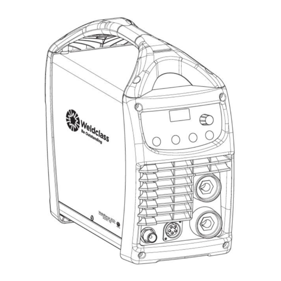
Page 8: Know Your Machine
4. Fuse 5. Water Cooler Interface 6. Remote Control Interface Figure 1 3.2 Machine Front 1. Positive Dinse Socket 2. Negative Dinse Socket 3. TIG torch Interface Connector 4. TIG Torch Gas Connector Figure 2 © Weldclass 2020 | E.&O.E. -
Page 9: Control Panel
Post-Gas Indicator Light ( [sec] n. SmartStart AC ( [A-sec] 8. Remote Control Indicator Light 9. Selection Knob 10. LCD Readout 11. Input Power Indicator Light 12. Error/Over Temperature Indicator Light Figure 3 © Weldclass 2020 | E.&O.E. -
Page 10: Tig Torch Controls
3.4 TIG Torch Controls 1. Torch Trigger Button 2. Remote Control Amperage Potentiometer Figure 4 © Weldclass 2020 | E.&O.E. -
Page 11: Symbols Chart
– Spot Weld Function Negative Pulse Function Positive Alternating Output Hertz (cycles/sec) Current (AC) Bi-Level Trigger Duty Cycle Amperage Smart Start AC (Current) AC Arc Balance Voltage Table 2 2T/Normal Trigger Function 4T/Latch Trigger Function © Weldclass 2020 | E.&O.E. -
Page 12: Controls Explained
4 CONTROLS EXPLAINED 4.1 Weld Process Selection 1. Press ‘Current Selection Button’ until the desired Indicator Light is lit. Figure 5 4.1.1 MMA Stick/MMA welding 4.1.2 TIG HF High Frequency Start TIG welding. This uses a high frequency arc to start the welding arc which eliminates the need for the tungsten electrode to make contact with the job. -
Page 13: Output Current Mode Selection
See 12.3.2 for more information. © Weldclass 2020 | E.&O.E. -
Page 14: Function Selection
) whilst welding using the torch trigger. 4t Trigger Mode must be selected to enable Bi-Level selection. During welding a quick press of the trigger will toggle between I current setting and I current setting. © Weldclass 2020 | E.&O.E. -
Page 15: Trigger Mode Selection
When the trigger button is pressed and held down on the TIG torch, the machine will weld for the set time and then stop. This is great for producing very precise weld size or ensuring consistent weld size/length when spot welding, tacking or stitch welding. © Weldclass 2020 | E.&O.E. -
Page 16: Tig Arc Parameters/Characteristics Settings
Start Amps to Main Amps. 4.5.4 Main Amps (7d) Main Amps (or Main Current or I ) is the main welding current. In Pulse and Bi-Level modes it represents the Maximum current. Adjustable 5-200A. © Weldclass 2020 | E.&O.E. -
Page 17: Base Amps (7E)
This effect can also be used to reduce heat in the tungsten, allowing use of a pointed tungsten tip shape for a more defined arc. See 12.3.4 for more information. Setting Value Weld Wave Effects More cleaning effect Positive Less penetration O (zero) Neutral Less cleaning effect Negative More penetration © Weldclass 2020 | E.&O.E. -
Page 18: Spot Time (7H)
The machine will ‘beep’ and flash up the Electrode diameter as the operator adjusts through the settings ranges to make it easier to set within recommended ranges. Electrode Recommended Setting Range Diameter From 1.0mm 1.6mm 2.4mm 18.8 19.8 3.2mm 32.8 34.8 © Weldclass 2020 | E.&O.E. -
Page 19: Remote Controls
4.6 Remote Controls 4.6.1 Remote Control TIG Torch The TIG torch supplied with the Weldforce 202T AC/DC machine incorporates a Remote Control Amperage Potentiometer on the handle. This can be used to change the Main Amps either before or during welding. -
Page 20: Mma/Stick Arc Parameters/Characteristics Settings
0 is Arc Force off, 100 is maximum Arc Force. This is practically useful for electrode types that have a higher operating voltage requirement or joint types that require a short arc length such as out of position welds. © Weldclass 2020 | E.&O.E. -
Page 21: Vrd Function (Mma / Stick)
Table 3 If you are unable to resolve the error by restarting the machine or with any of the above solutions, contact your Weldforce distributor to arrange to have the machine assessed by a technician. © Weldclass 2020 | E.&O.E. -
Page 22: Power Supply
5 POWER SUPPLY 5.1 Electrical Connection The Weldforce 202T is factory-fitted with a 10A 240V plug for commissioning purposes. Whilst 10A plug is fitted, the operator must set to 10A (LC.2) mode and ensure that output and duty cycle limits indicated in Table 1 (under section 2 of this manual) are not exceeded. -
Page 23: Generator Use
For further information please refer to AS 60529. Ventilation Adequate ventilation is required to provide proper cooling for the machine. Ensure that the machine is placed on a stable level surface where clean cool air can easily flow through the unit. © Weldclass 2020 | E.&O.E. -
Page 24: Basic Setup
6. Select the required output current using the Selection Knob (9). The LCD Readout (10) will display the set amperage output. 7. Adjust special Function settings if required 8. You are now ready to weld! Figure 12 © Weldclass 2020 | E.&O.E. -
Page 25: Tig Welding Setup
HF current feedback through the torch. (Remote adaptor Not required if using torch with switch only, without remote amperage control) Figure 13 © Weldclass 2020 | E.&O.E. -
Page 26: Accessories, Spare Parts & Circuit Diagrams
TIG Ceramic Cup - #8 12.7mm Pk2 P3-10N45 TIG Ceramic Cup - #10 15.8mm Pk2 WC-05192 TIG Tungsten RE4 – 1.6mm Pk10 WC-05193 TIG Tungsten RE4 – 2.4mm Pk10 WC-05194 TIG Tungsten RE4 – 3.2mm Pk10 Figure 14 Table 4 © Weldclass 2020 | E.&O.E. -
Page 27: Optional Accessories
WC-04676 TIG Gloves WC-01775 Welding Gloves WC-06370 Remote Foot Control Table 5 8.3 Machine Spare Parts: For machine parts, go to www.weldclass.com.au/machines or contact your Weldclass distributor. Ref. Description Ref. Description IGBT Transistor Hall Sensor Gas Discharger IGBT Transistor Capacitor... - Page 28 Figure 15 © Weldclass 2020 | E.&O.E.
-
Page 29: Primary Schematic Circuit Diagram
Weldforce 202 T AC/DC 8.4 Primary Schematic Circuit Diagram Figure 16 8.5 Torch Control Schematic Circuit Diagram Figure 17 © Weldclass 2020 | E.&O.E. -
Page 30: Care & Maintenance
9 CARE & MAINTENANCE 9.1 Keep your Welding Machine in Top Condition The Weldforce 202T AC/DC does not require any special maintenance, however the user should take care of the machine as follows: 1. Regularly clean the ventilation slots 2. Keep the casing clean 3. -
Page 31: General Guide To Welding
10.2.1.5 Materials MMA welding can be used with a wide variety of electrodes including general purpose, low hydrogen, stainless steel, iron powder, hard facing & cast iron just to name a few. © Weldclass 2020 | E.&O.E. -
Page 32: The Tig Process
10.2.2.5 Materials This machine incorporates AC/DC TIG function which can be used to weld a variety of materials including mild steels, stainless steels, copper and chrome moly, aluminium, titanium and zinc. © Weldclass 2020 | E.&O.E. -
Page 33: Joint Preparations
Slag should be removed from oxy-cut surfaces. Typical joint designs are shown in the following figures. Figure 22 Figure 18 Figure 23 Figure 19 Figure 24 Figure 20 Figure 25 Figure 21 Figure 26 © Weldclass 2020 | E.&O.E. - Page 34 Figure 27 © Weldclass 2020 | E.&O.E.
-
Page 35: Stick (Mma) Basic Welding Guide
Most types of cast iron, except white iron, are weldable. White iron, because of its extreme brittleness, generally cracks when attempts are made to weld it. Trouble may also be experienced when welding white-heart malleable, due to the porosity caused by gas held in this type of iron. © Weldclass 2020 | E.&O.E. -
Page 36: Types Of Electrodes
11.5.1 Mild Steel 1. General Purpose “GP” E6013 (Weldclass 12V): This all-position electrode is used for maintenance and fabrication. Works well on mild steel, galvanized steel, sheet metal, steel tube and RHS. -
Page 37: Mma Welding Techniques
Another difficulty you may meet is the tendency, after the arc is struck, to withdraw the electrode so far that the arc is broken again. A little practice will soon remedy both of these faults. Figure 28 © Weldclass 2020 | E.&O.E. -
Page 38: Arc Length
If the travel is too fast, the bead will be narrow and strung out and may even be broken up into individual globules. If the travel is too slow, the weld metal piles up and the bead will be too large. © Weldclass 2020 | E.&O.E. -
Page 39: Making Welded Joints
Plates thicker than 6.0mm should have their mating edges beveled to form a 70º to 90º included angle. This allows full penetration of the weld metal to the root. Using a 3.2mm Weldclass 12V Stick electrode at 100 amps, deposit a run of weld metal on the bottom of the joint. -
Page 40: Fillet Welds
A piece of angle iron is a suitable specimen with which to begin, or two lengths of strip steel may be tacked together at right angles. Using a 3.2mm Weldclass 12V Stick electrode at 100 amps, position angle iron with one leg horizontal and the other vertical. This is known as a horizontal-vertical (HV) fillet. -
Page 41: Vertical Welds
Tack weld a three feet length of angle iron to your work bench in an upright position. Use a 3.2mm Weldclass 12V Stick electrode and set the current at 100 amps. Make yourself comfortable on a seat in front of the job and strike the arc in the corner of the fillet. The electrode needs to be about 10º... -
Page 42: Overhead Welds
Use a 3.2mm Weldclass 12V Stick electrode at 100 amps, and deposit the first run by simply drawing the electrode along at a steady rate. You will notice that the weld deposit is rather convex, due to the effect of gravity before the metal freezes. -
Page 43: Mma (Stick) Troubleshooting
Insufficient deposit time at Pause for a moment at edge of edge of weave. weave to allow weld metal build-up. Power source is set for MIG Set power source to STICK (GMAW) welding. (MMA) mode. © Weldclass 2020 | E.&O.E. - Page 44 Redesign to relieve weld joint soon after solidification severe crack commences resistance electrodes. Insufficient throat thickness. Travel slightly slower to allow greater build up in throat. Weld current is too high. Decrease welding current. Figure 42 Table 8 © Weldclass 2020 | E.&O.E.
-
Page 45: Tig Basic Welding Guide
Filler Electrode Diameter DC Current (Amps) 1.6mm (1/16”) 60 – 115 1.6mm (1/16”) 20 – 90 2.4mm (3/32”) 100 – 165 2.4mm (3/32”) 65 – 115 3.2mm (1/8”) 135 – 200 3.2mm (1/8”) 100 – 165 Table 10 Table 11 © Weldclass 2020 | E.&O.E. -
Page 46: Preparing Tungsten
12.1.2 Preparing Tungsten The electrode should be pointed (tapered) according to the welding current. Grind end of tungsten on fine grit, hard abrasive wheel before welding. Do not use wheel for other jobs or tungsten can become contaminated causing lower weld quality. Rule of thumb is that the taper section should be 2.5 times the Electrode Diameter. -
Page 47: Shielding Gas For Tig Welding
AC Current (Amps) Argon Gas Electrode Flow Rate Unbalanced Balanced Diameter L/min Wave Wave 1.0mm (0.040”) 15-80 20-60 5 - 10 1.6mm (1/16”) 70-150 60-120 10 - 15 2.4mm (3/32”) 140-235 100-180 10 - 15 Table 15 © Weldclass 2020 | E.&O.E. -
Page 48: Starting The Weld
4. If set to 4T Trigger mode the Start Current will be maintained until you release the Torch Trigger Button and will then proceed to the Slope-Up process. If Set to 2T Trigger mode machine will begin with Start Current briefly then proceed to the Slope-Up process. © Weldclass 2020 | E.&O.E. -
Page 49: Main Weld Current
AC is used for welding the following materials: • Aluminium • Aluminium Alloys • Magnesium • Zinc Figure 48 © Weldclass 2020 | E.&O.E. -
Page 50: Pulse Welding
Pulse Width percentage increase the time that is spent at the Main Current which in turn increases the heat input into the job. Inversely reducing the Pulse Width percentage means more time is spent at the Base Current which reduces heat input. Figure 49 © Weldclass 2020 | E.&O.E. -
Page 51: Ac Balance
The cleaner the non-ferrous metal is before welding, the more effective it is to weld. This effect can also be used to reduce heat in the tungsten, allowing use of a pointed tungsten tip shape for a more defined arc. Figure 50 Figure 51 © Weldclass 2020 | E.&O.E. -
Page 52: Finishing The Weld
12.4.3 Finish Amps This gives a selected small amount of current which the operator can use to neatly complete the end of the weld. © Weldclass 2020 | E.&O.E. -
Page 53: Tig Welding Troubleshooting
Select the right shielding gas. used. Poor Work Lead/Clamp Improve connection to work piece. connection to work piece. Arc flutters during TIG welding. Tungsten electrode is too large Select the right size electrode. for the welding current. Table 16 © Weldclass 2020 | E.&O.E. -
Page 54: Knowledge & Resources
14.3 Welding Operation 1. Maintain labels and nameplates on the welder. These carry important information. If unreadable or missing, contact Weldclass for a replacement. 2. Avoid unintentional starting. Make sure the welder is setup correctly and you are prepared to begin work before turning on the welder. - Page 55 12. Do not use this machine for pipe thawing. This machine was not designed for pipe thawing and will be a significant electrical & heat hazard if attempt is made to use for thawing pipe. © Weldclass 2020 | E.&O.E.
-
Page 56: Welding Safety Instructions & Warnings
This will ensure that the safety of the power tool is maintained. 14.4.1 Personal Safety CAUTION! Keep the work area well lit. Make sure there is adequate space surrounding the work area. Always keep the work area free of obstructions, grease, © Weldclass 2020 | E.&O.E. -
Page 57: Arc Rays Can Burn Eyes And Skin
DANGER! Remove any combustible material from the work area. 1. When possible, move the work to a location well away from combustible materials. If relocation is not possible, protect the combustibles with a cover made of fire resistant material. © Weldclass 2020 | E.&O.E. -
Page 58: Electricity Can Kill
Arc rays from the welding process produce intense heat and strong ultraviolet rays that can burn eyes and skin. Use the following table to select the appropriate shade number for a Welding Helmet or Welding Face © Weldclass 2020 | E.&O.E. -
Page 59: Fumes And Gases
5. Watch for fire, and keep a fire extinguisher nearby. 6. Be aware that welding on a ceiling, floor, bulkhead, or partition can cause fire on the hidden side. 7. Do not weld on closed containers such as tanks or drums. © Weldclass 2020 | E.&O.E. -
Page 60: Sparks & Hot Metal
6. Turn your face away from the valve outlet when opening the cylinder valve. WARRANTY 15.1 Warranty Information For full details on warranty period and terms and conditions, go to www.weldclass.com.au/WarrantyInfo © Weldclass 2020 | E.&O.E.
Need help?
Do you have a question about the Weldforce 202T and is the answer not in the manual?
Questions and answers