Table of Contents
Advertisement
Quick Links
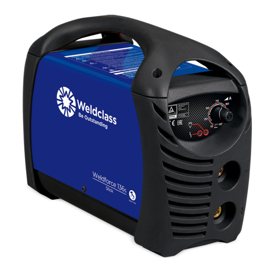
Weldforce 136S
Weldforce 181S
OPERATING INSTRUCTIONS
Edition 1.5
IMPORTANT!
To qualify for full / extended warranty, you must register within 30 days of purchase. See inside for details.
Read these Operating Instructions Completely before attempting to use this machine. Save this manual and
keep it handy for quick reference. Pay particular attention to the safety instructions we have provided for
your protection. Contact your distributor if you do not fully understand anything in this manual.
Advertisement
Table of Contents

Related Manuals for Weldclass Weldforce 136S


Summary of Contents for Weldclass Weldforce 136S
- Page 1 Weldforce 136S Weldforce 181S OPERATING INSTRUCTIONS Edition 1.5 IMPORTANT! To qualify for full / extended warranty, you must register within 30 days of purchase. See inside for details. Read these Operating Instructions Completely before attempting to use this machine. Save this manual and keep it handy for quick reference.
- Page 2 Congratulations & thank you for choosing Weldclass! The Weldforce range from Weldclass provides market leading value, features and durability. Register Your Warranty Now To qualify for an extended warranty, you must register within 30 days of purchase. Full details on warranty period and terms can be found at www.weldclass.com.au/WarrantyInfo...
-
Page 3: Table Of Contents
Weldforce 136S & 181S 1 CONTENTS CONTENTS ............................... 3 BASIC SPECIFICATIONS ..........................5 KNOW YOUR MACHINE ........................... 6 Machine Front ..........................6 Machine Rear ..........................6 Symbols chart ..........................7 CONTROLS EXPLAINED ..........................8 Setting Selection ..........................8 Error/Over Temperature Indicator Light ..................8 POWER SUPPLY ............................ - Page 4 Noise Can Damage Hearing ....................33 13.4.4 Work Environment Safety ....................34 13.4.5 Electricity Can Kill .........................34 13.4.6 Fumes And Gases .........................35 13.4.7 Fire & Explosive Risks ......................36 13.4.8 Sparks & Hot Metal ......................36 WARRANTY ............................36 14.1 Warranty Information ........................36 © Weldclass | E.&O.E.
-
Page 5: Basic Specifications
Weldforce 136S & 181S 2 BASIC SPECIFICATIONS Description WeldForce 136S WeldForce 181S Part Number WC-136S WC-181S Dimensions of Power Source (L x 300 x 125 x 255mm 300 x 130 x 230mm W x H) Weight of Power Source 2.8kg 4.1kg... -
Page 6: Know Your Machine
2. Error/Over Temperature Indicator Light 3. Power On Indicator Light 4. Adjustment Knob 5. Negative (-) Welding Power Output Connection Socket Figure 1 3.2 Machine Rear 1. Mains Power Switch 2. 240V AC Mains Power Input Lead Figure 2 © Weldclass | E.&O.E. -
Page 7: Symbols Chart
Weldforce 136S & 181S 3.3 Symbols chart Power Supply Power On Connection Power Off Single Phase Power On Direct Current (DC) Indication ꝇ – Fault Indication Negative Caution / Hazard Positive Read Instruction Hertz (cycles/sec) Manual Increase/Decrease Duty Cycle Single phase... -
Page 8: Controls Explained
Anti-Stick Protection: automatically shuts down the welding machine if the electrode sticks to the material being welded so that it can be removed manually without damaging the electrode holder. This may also activate if there are electronic circuit failure issues. Figure 5 © Weldclass | E.&O.E. -
Page 9: Power Supply
Weldforce 136S & 181S 5 POWER SUPPLY 5.1 Electrical Connection Weldforce 136S The Weldforce 140ST is designed to operate on a 10A 240V AC power supply. Weldforce 181S The Weldforce 181S is designed to operate on a 15A 240V AC power supply. -
Page 10: Golden Rules Of Generator Use
For further information please refer to AS 60529. Ventilation Adequate ventilation is required to provide proper cooling for the machine. Ensure that the machine is placed on a stable level surface where clean cool air can easily flow through the unit. © Weldclass | E.&O.E. -
Page 11: Basic Operation
Weldforce 136S & 181S 7 BASIC OPERATION 7.1 Stick (MMA) Welding Operation 1. Connect the earth cable quick connector to the Negative (-) Welding Power Output Socket (5) 2. Connect the earth clamp to the work piece. Contact with the work piece must be firm contact with clean, bare metal, with no corrosion, paint or scale at the contact point. -
Page 12: Accessories, Spare Parts & Circuit Diagrams
Optional Accessories Part No. Accessory WC-06235 Welding Trolley WC-01775 Welding Gloves Table 3 8.2 Machine Spare Parts: For machine parts, go to www.weldclass.com.au/machines or contact your Weldclass distributor. Weldforce 136S Weldforce 181S Ref. Description Ref. Description Potentiometer Potentiometer Resistor Resistor... - Page 13 Weldforce 136S & 181S Table 5 Weldforce 136S Figure 7 © Weldclass | E.&O.E.
- Page 14 Weldforce 181S Figure 8 © Weldclass | E.&O.E.
-
Page 15: Primary Schematic Circuit Diagram
Weldforce 136S & 181S 8.3 Primary Schematic Circuit Diagram Weldforce 136S & 181S Figure 9 © Weldclass | E.&O.E. -
Page 16: Care & Maintenance
Use only genuine replacement parts. Do not use modified or non-genuine parts. 9.2 Storing the Welder When not in use the welder should be stored in the dry, dust-free and frost-free environment. © Weldclass | E.&O.E. -
Page 17: General Guide To Welding
Weldforce 136S & 181S 10 GENERAL GUIDE TO WELDING 10.1 Duty Cycle Rating WeldForce welding machines are fitted with thermal overload protection which means the machine will cut out when it reaches a certain temperature, to prevent damage to components. The machine will then re-start when it returns to a safe temperature. -
Page 18: Joint Preparations
Slag should be removed from oxy-cut surfaces. Typical joint designs are shown in the following figures. Figure 14 Figure 10 Figure 15 Figure 11 Figure 16 Figure 12 Figure 17 Figure 13 Figure 18 © Weldclass | E.&O.E. - Page 19 Weldforce 136S & 181S Figure 19 © Weldclass | E.&O.E.
-
Page 20: Stick (Mma) Basic Welding Guide
Most types of cast iron, except white iron, are weldable. White iron, because of its extreme brittleness, generally cracks when attempts are made to weld it. Trouble may also be experienced when welding white-heart malleable, due to the porosity caused by gas held in this type of iron. © Weldclass | E.&O.E. -
Page 21: Types Of Electrodes
11.5.1 MILD STEEL: 1. General Purpose “GP” E6013 (Weldclass 12V): This all-position electrode is used for maintenance and fabrication. Works well on mild steel, galvanized steel, sheet metal, steel tube and RHS. -
Page 22: Mma Welding Techniques
Another difficulty you may meet is the tendency, after the arc is struck, to withdraw the electrode so far that the arc is broken again. A little practice will soon remedy both of these faults. Figure 20 © Weldclass | E.&O.E. -
Page 23: Arc Length
Weldforce 136S & 181S 11.7.4 Arc Length As soon as the arc is established, maintain a 1.6mm to 3.2mm gap between the burning electrode end and the parent metal. Draw the electrode slowly along as it melts down. The securing of an arc length necessary to produce a neat weld soon becomes almost automatic. -
Page 24: Making Welded Joints
Plates thicker than 6.0mm should have their mating edges beveled to form a 70º to 90º included angle. This allows full penetration of the weld metal to the root. Using a 3.2mm Weldclass 12V Stick electrode at 100 amps, deposit a run of weld metal on the bottom of the joint. -
Page 25: Fillet Welds
A piece of angle iron is a suitable specimen with which to begin, or two lengths of strip steel may be tacked together at right angles. Using a 3.2mm Weldclass 12V Stick electrode at 100 amps, position angle iron with one leg horizontal and the other vertical. This is known as a horizontal-vertical (HV) fillet. -
Page 26: Vertical Welds
Tack weld a three feet length of angle iron to your work bench in an upright position. Use a 3.2mm Weldclass 12V Stick electrode and set the current at 100 amps. Make yourself comfortable on a seat in front of the job and strike the arc in the corner of the fillet. The electrode needs to be about 10º... -
Page 27: Overhead Welds
Use a 3.2mm Weldclass 12V Stick electrode at 100 amps, and deposit the first run by simply drawing the electrode along at a steady rate. You will notice that the weld deposit is rather convex, due to the effect of gravity before the metal freezes. -
Page 28: Mma (Stick) Troubleshooting
Figure 31 Electrode too large for joint. Use smaller gauge electrode. Insufficient deposit time at Pause for a moment at edge of edge of weave. weave to allow weld metal build-up. © Weldclass | E.&O.E. - Page 29 Weldforce 136S & 181S Fault Cause Remedy Portions of the weld run do Small electrodes used on heavy Use larger electrodes and not fuse to the surface of the cold plate. preheat the plate. metal or edge of the joint.
-
Page 30: Knowledge & Resources
13.3 Welding Operation 1. Maintain labels and nameplates on the welder. These carry important information. If unreadable or missing, contact Weldclass for a replacement. 2. Avoid unintentional starting. Make sure the welder is setup correctly and you are prepared to begin work before turning on the welder. - Page 31 Weldforce 136S & 181S 4. Never leave the welder unattended while energised. Turn power off before leaving the welder unattended. 5. Do not touch live electrical parts. Wear dry, insulating gloves. Do not touch the electrode or the conductor tong with bare hands. Do not wear wet or damaged gloves.
-
Page 32: Welding Safety Instructions & Warnings
CAUTION! Heavy-duty work gloves, non-skid safety shoes and hearing protection used for appropriate conditions will reduce personal injuries. CAUTION! Have the equipment serviced by a qualified repair person using identical replacement parts. This will ensure that the safety of the power tool is maintained. © Weldclass | E.&O.E. -
Page 33: Personal Safety
Weldforce 136S & 181S 13.4.1 Personal Safety CAUTION! Keep the work area well lit. Make sure there is adequate space surrounding the work area. Always keep the work area free of obstructions, grease, oil, trash, and other debris. Do not use equipment in areas near flammable chemicals, dust, and vapours. -
Page 34: Work Environment Safety
3. Insulate yourself from the work and the ground using dry insulating mats or covers. 4. Disconnect input power before installing or servicing this equipment. Lock input power, disconnect switch open, or remove line fuses so power cannot be turned on accidentally. © Weldclass | E.&O.E. -
Page 35: Fumes And Gases
Weldforce 136S & 181S 5. Properly install and ground this equipment according to national, state, and local codes. 6. Turn off all equipment when not in use. Disconnect power to equipment if it will be left unattended or out of service. -
Page 36: Fire & Explosive Risks
1. Wear an AS/NZS approved face shield or safety goggles. Side shields are recommended. 2. Wear appropriate safety equipment to protect the skin and body. 14 WARRANTY 14.1 Warranty Information For full details on warranty period and terms and conditions, go to www.weldclass.com.au/WarrantyInfo © Weldclass | E.&O.E.
Need help?
Do you have a question about the Weldforce 136S and is the answer not in the manual?
Questions and answers