Table of Contents
Advertisement
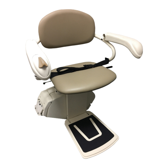
Pinnacle Stair Lift
SL300 / SL300FR
INSTALLATION MANUAL
ATTENTION! STRICT ADHERENCE TO THESE INSTALLATION INSTRUCTIONS is required and will promote the safety of those installing this
product, as well as those who will ultimately use the lift for its intended purpose. Any deviation from these instructions will void the
LIMITED WARRANTY that accompanies the product. Additionally, any party installing the product who deviates from the INSTALLATION
INSTRUCTIONS shall be taken to agree to INDEMNIFY, SAVE AND HOLD HARMLESS the manufacturer from any and all loss, liability or
damage, including attorneys fees, that might arise out of or in connection with such deviation.
72618 P/N: 630-00100 Rev E
Advertisement
Table of Contents

Related Manuals for Harmar Mobility Pinnacle Series


Summary of Contents for Harmar Mobility Pinnacle Series
- Page 1 Pinnacle Stair Lift SL300 / SL300FR INSTALLATION MANUAL ATTENTION! STRICT ADHERENCE TO THESE INSTALLATION INSTRUCTIONS is required and will promote the safety of those installing this product, as well as those who will ultimately use the lift for its intended purpose. Any deviation from these instructions will void the LIMITED WARRANTY that accompanies the product.
-
Page 2: Table Of Contents
Pinnacle SL300 CONTENTS Contents Read and understand this manual prior to attempting stair lift installations. Please refer PRELIMINARY CHECKS to the Owner’s Manual for Limited Warranty information and operating instructions. The Owner’s Tools Required ....... 3 Manual must be reviewed with and given to the owner Included Parts . -
Page 3: Preliminary Checks
Pinnacle SL300 PRELIMINARY CHECKS Rail Box: Bottom rail pre-installed with: Bottom end plate Charge strip wire harness Bottom limit cam Joint pins and joint brackets Tools Required (two-piece rail only) The following is a suggested list of basic tools to Plastic gear rack have on hand during installation. -
Page 4: Installation Procedures
Pinnacle SL300 INSTALLATION PROCEDURES A. DETERMINE OVERALL RAIL LENGTH (Only if rail did not come pre-cut to length) 1. Determine any obstructions that will affect the position and length of the rail. These may include walls, doors, hallway orientation, etc. 2. -
Page 5: Rail Installation
Pinnacle SL300 INSTALLATION PROCEDURES B. RAIL INSTALLATION 1. Open the rail box and remove the contents. 2. Position the bottom rail (the rail with end plate attached) directly on the stairs with the end plate towards the bottom of the stairs and the plastic rack facing up. - Page 6 Pinnacle SL300 INSTALLATION PROCEDURES A. For double rails, the first rail bracket should be tightened in place so when turned over the back of the bracket touches the rear of the first step from the bottom landing. The second and third brackets should be placed and tightened on the steps on each side of the rail joint, again so the back of the bracket touches the rear of the step.
-
Page 7: Chassis Installation
Pinnacle SL300 INSTALLATION PROCEDURES C. CHASSIS INSTALLATION 1. Remove chassis from box. Lift the chassis with the manual override hole (on bottom) facing the downhill side of the stairs and gently slide the chassis onto the rail until it makes contact with the plastic rack. -
Page 8: Final Rail Installation
Pinnacle SL300 INSTALLATION PROCEDURES D. FINAL RAIL INSTALLATION 1. Install the remaining plastic rack pieces in the upper rail. [Figure 8-1] 2. Use a hacksaw or chop saw to cut the last plastic rack piece flush with the rail end. Place something on the floor to catch debris or mark and cut the rack outside. - Page 9 Pinnacle SL300 INSTALLATION PROCEDURES 5. Install the end plate to the top of the track with the four (4) self-cutting Torx screws using the supplied T30 Torx bit. [Figure 9-1] Too much torque applied to these screws may result in damage. Take your time and apply grease to threads.
-
Page 10: Footrest And Seat Installation
Pinnacle SL300 INSTALLATION PROCEDURES E. FOOTREST & SEAT INSTALLATION 1. Use the installation switch to drive the chassis down to the bottom step. This will provide a safe area to install and adjust the footrest. DO NOT drive the unit into bottom stop. 2. -
Page 11: Procedure To Switch Armrest Control
Pinnacle SL300 INSTALLATION PROCEDURES 8. Position the seat directly aligned over the carriage and place onto the seat swivel post. Depress the swivel lever until the seat is fully engaged with the swivel post. Check the swivel lever to test the locking mechanism. THE SYSTEM WILL NOT FUNCTION IF PROPER ENGAGEMENT IS NOT ACHIEVED. -
Page 12: Audible Tones
Pinnacle SL300 INSTALLATION PROCEDURES H. TONES INFORMATION Minor faults G. AUDIBLE TONES Single long beep (will reset once fault is cleared) • Seat swiveled out of position If the lift does not operate, check the safety senors: • Edge safety detected Seat swivel sensor (seat should be in the •... -
Page 13: Remote Control Operation
Pinnacle SL300 REMOTE CONTROL OPERATION Remote Call/Send Control Operation A. REMOTE CONTROL OPERATION B. REMOTE CONTROL RE-PROGRAMMING All call/send controls are factory programmed. 1. Press and hold the Re-programming is not normally necessary during appropriate directional installation. button on the front of the hand control. -
Page 14: Completion Procedures
Pinnacle SL300 COMPLETION PROCEDURES Completion Procedures 2. The final stopped position can be adjusted to accommodate the height of the user by repositioning the limit cam located in a slot in the rail. A. TEST ARMREST CONTROL SWITCH 3. Use a 5/64" Allen wrench to loosen the set screw 1. -
Page 15: Additional System Checks
Pinnacle SL300 COMPLETION PROCEDURES 7. Repeat the above tests while driving the lift in opposite direction. 8. If any safety condition does not function properly, carefully review all installation instructions, reset the “ON /OFF” switch. Repeat the above tests. 9. If any safety stop switch fails to immediately stop the lift, immediately call the manufacturer for assistance in diagnosing and repairing the problem. -
Page 16: Folding Rail Installation
Pinnacle SL300 FOLDING RAIL INSTALLATION Folding Rail Installation Note - The photos in this section show a "left" folding rail, assembled to be installed on the left side of the stairway. If you’re assembling a "right’"side, please complete all of these steps in mirror-image to what’s shown. - Page 17 Pinnacle SL300 FOLDING RAIL INSTALLATION 4. Place the rail onto the stairway with the bottom bracket on the second step, as shown. Note that the bottom feet should approximately rest on the floor with the rail straight, but they will be adjusted later. [Figure 17-1] 5.
- Page 18 Pinnacle SL300 FOLDING RAIL INSTALLATION 7. Fasten down the near corner of the lower bracket using a drill that has extensions at least 10" long and a 3/8" socket. [Figure 18-1 & 18-2] 8. Measure from the side of the rail at the upper bracket of the folding rail.
-
Page 19: Folding Rail Installation
Pinnacle SL300 FOLDING RAIL INSTALLATION 12. Reinstall the two plastic caps on the feet to cover the threads [Figure 19-1] 13. Carefully move the fork with your hand to make sure it operates smoothly. Allow it to go all the way to the floor. -
Page 20: Technical Specifications
Pinnacle SL300 FOLDING RAIL INSTALLATION TECHNICAL SPECIFICATIONS Technical Specifications Weight Capacity 300 lb Track (Rail) Type Aluminum Extrusion Travel 15'6" standard - 32' max Avg. # of Return Trips per Charge Minimum Folded Width 11.0" / 13.0" Folding Rail Minimum Footrest Height 2.5"... -
Page 21: End-User Familiarization
Pinnacle SL300 TECHNICAL SPECIFICATIONS FOLDING RAIL INSTALLATION FAMILIARIZATION It is very important to familiarize the customer with the stairlift as the final step in installation. To acheive this, walk the customer through the Owner's Manual. 1. Present the unit from seat, controls, footrest, track, on / off switch, call / sends, and power supply. -
Page 22: Notes
Pinnacle SL300 NOTES NOTES | www.harmar.com © 2018Harmar Mobility, LLC • All Rights Reserved... - Page 23 Pinnacle SL300 NOTES SL300 • Pinnacle Stair Lift Installation Manual 72618 P/N: 630-00100 Rev E...
- Page 24 Pinnacle Stair Lift SL300 / SL300FR www.harmar.com | 800-833-0478 INSTALLATION MANUAL 2075 47th Street Sarasota, Florida 34234 72618 P/N: 630-00100 Rev E...
Need help?
Do you have a question about the Pinnacle Series and is the answer not in the manual?
Questions and answers
I have a harmar sl300 stair lift I need a wire harness that goes from the up and down switch on the arm rest to base how can I get one
To obtain a wire harness for the Harmar SL300 stair lift that connects the up and down switch on the armrest to the base, you should contact Harmar technical services at techservices@harmar.com.
This answer is automatically generated