
Subscribe to Our Youtube Channel
Related Manuals for wiwa PHOENIX 6530


Summary of Contents for wiwa PHOENIX 6530
- Page 1 Operation manual WIWA PHOENIX ❍ Airless Type: ❍ Air-Combi ❍ 6530 ❍ 6552 ❍ 11018 ❍ 11032 Serial-No. … … … … … … … … ❍ Hot Job Translation of original operation manual WIWA Phoenix Phoenix · DBE · en · 02.12 · jw...
-
Page 2: Table Of Contents
Maintenance plan Copyright ownership for this user manual remains with High pressure filter WIWA WILHELM WAGNER GmbH & Co. KG Maintenance unit or Regulator Cluster Gewerbestraße 1-3 • 35633 Lahnau Phone: +49 (0)6441 609-0 • Fax: +49 (0)6441 609-50 • E-mail: info@ wiwa.de •... -
Page 3: Safety
Safety Description of symbols Warnings located on the pump The signs and symbols used in this User's Handbook have Warning signs and symbols which have been placed on the following meaning: the unit are there to inform of possible dangers and must be observed. -
Page 4: Applications For The Pump
Safety It left the factory in perfect condition and warrants a high Dangerous chemical reactions can occur if closed or level of safety. However, the following dangers exist if pressurized systems with aluminum or galvanized pump operated incorrectly or used inappropriately: components come into contact with solvents such as risk of physical injury or death to the operator or third 1.1.1 - trichlorethylene or methylene chloride that contain... -
Page 5: Pump Surroundings
Safety It must be ensured that Emissions the pump is grounded It is possible for solvent vapours to occur, depending on separately or together the materials used. with the equipment it is Therefore, please ensure the workplace is sufficiently mounted to (maximum ventilated in order to avoid damage to health and property. -
Page 6: Wiwa Wilhelm Wagner Gmbh & Co.kg
Safety Operating staff The maximum operating pressure stated by us must correspond to all components and Authorised Operators accessory items within the system (i.e. pumps, People under the age of 16 should not operate this equip- heaters, hoses, spray guns, safety valves). ment. -
Page 7: Behavior In Case Of Emergency
Safety High-pressure spray equipment can be installed inside Memorize the local emergency phone numbers. ➤ ➤ or outside of spray booths and spray rooms. To avoid Become familier with the first-aid measures ➤ pollution, an outside installation is preferable. The Fires dimensions and weight of the unit can be found in Chapter 11.1 Technical specifications. -
Page 8: Copyright
Safety Checklist for checking the safety devices with the system depressurized Check to see whether the seal on the safety valve is ➤ damaged. Check the safety valve for signs of damage. ➤ Check the ground cable for damage. ➤ Check the connctions for the ground cable on the unit ➤... -
Page 9: Wiwa.de • Internet: Www.wiwa.de
Safety 2.12 Transporting Disconnect the unit from the main air supply and from ➤ any electrical outlets for accessory items, even if the unit is only to me moved a short distance. Empty the unit before transporting. ➤ Be careful when using a hoist to load this equipment! ➤... -
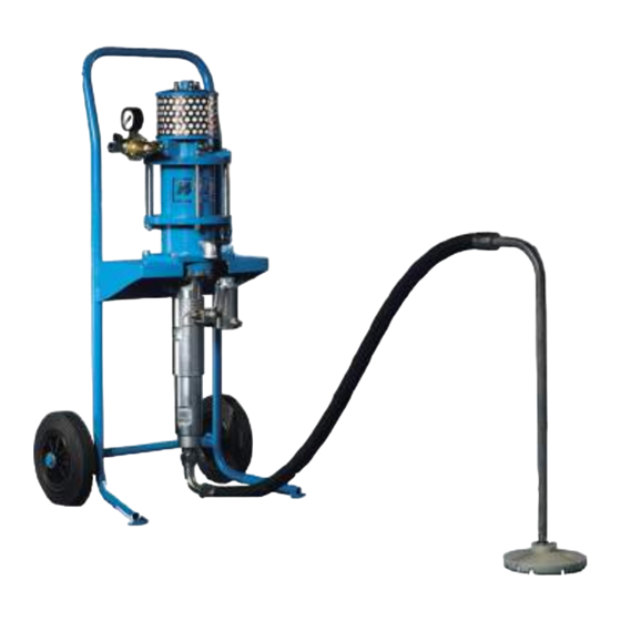
Page 10: Component Description
Component description Phoenix - Airless - cart version Phoenix - Airless - funnel version Positions cart frame air motor air pressure regulator with air tap lock and compres- sed air connection nipple vent hole high pressure filter material pump suction pipe with strainer Phoenix-Hot Job - unit mind. -
Page 11: Installation And Assembly
Installation and Assembly Wall-mounted versions: To fix the wall-mount, use M 12 screws - class 8.8 ➤ Be sure to use anchoring devices in accordance with ➤ the nature of the wall being used Ensure that at least 10 cm (4 in.) free space is left ➤... - Page 12 Start-up 4 Open the ventilation hole When being used for the first ➤ time the sealing plug is to be removed from the venti- lation hole (overflow). The ventilation hole is located in the elbow with the openeing facing downward (picture 4.4, Pos.
-
Page 13: Start-Up
Start-up First cleaning 5. Clean the high-pressure filter Hold the drain hose (Picture ➤ 5.1.3, Pos. 2) into the container This machine was factory tested after assembly for perfect "B" and secure against slipping. functioning with a test-medium. The entire system should Open the drain valve (Picture be flushed with wash thinner before spray operation ➤... - Page 14 Start-up Chapter 2.6). 3. Check the safety valve Briefly raise the pressure approximately 10% above ➤ the maximum allowable inbound air pressure. The safety valve must blow off 4. Check the seal of the system components Check the seal of the following components: ➤...
-
Page 15: Operation
Operation Equipment preparation Clean the gun outlet with solvent and a brush. ➤ Mount a spraying tip or a reversible guard with the ➤ appropriate tip. Prepare the unit for operation. Observe and follow the instructions found in Prerequisite the User's Handbook for the spray gun being Required: used. -
Page 16: Change Of Material
Operation Change of material Coating / Finishing tips Hold the spray gun at a 90° angle to the surface being 1. Shut down the unit ➤ coated. If held at a different angle, the coverage will be Complete all steps for shutting down the pump found in ➤... -
Page 17: Shutting Down
Shutting down to maintain contact with the inner wall of the container. The unit is to be cleaned and taken out of service after Close the spray gun and apply the safety catch. ➤ work is completed. Lift the unit out of container "A". ➤... -
Page 18: Optional Versions
Optional versions Air Combi Air Combi unit Picture 8.1.3 Picture 8.1.4 Air Combi spray gun Paint container Spray hose air tap lock Air hose air pressure regulator Picture 8.1.1 air pressure connection air pressure regulator for Atomizing air With this method, the material being sprayed is fed to the air pressure connection from air-assisted airless (Air Combi) spray gun under moderate Air-Combi-unit to spray gun... -
Page 19: Hot Spray
➤ heater If residue solvent in the fluid heaters becomes warm, this can lead to an explosion causing WIWA Material Fluid Heater Picture 8.2.2 both injury and property damage. When using a fluid heater, observe the: Translation of the original operation manual Airless... - Page 20 Optional versions Operating pressure the "long way": up to the fluid pressure regulator. The drain valve at the high-pressure filter and the The fluid heater has a maximum operating pressure of 450 spray gun remain closed. bar /6525 psi (low-pressure versions = 200 bar / 2900 psi). Clean the fluid pressure regulator: close all drain The max.
-
Page 21: Maintenance
Maintenance Regular inspections According to the rules for the prevention of accidents „Working with liquid jet systems“ BGR 500, chapter 2.36 the equipment must be checked and overhauled at regular add release agent intervals by a air motor specialist ( Service). -
Page 22: Maintenance Unit Or Regulator Cluster
Maintenance Briefly trigger the spray gun. Filter insert selection ➤ To drain pressure, open the drain valve / screw on the ➤ The insert must: high-pressure filter. correspond to the material being sprayed ➤ Disassemble the high-pressure filter very carefully! ➤... - Page 23 Maintenance Adjustment of the fog oiler on the air maintenance unit Let the air motor run slowly at an air inlet pressure of ➤ approx.4 bar. Check the sight glass on the fog oiler to ensure that ➤ one drop of release agent is fed into the compressed air at every 10 - 15 double strokes of the air motor.
-
Page 24: Malfunctions And Troubleshooting
Malfunctions and troubleshooting Fault Solution Possible Cause The pump does not cycle whether the 1. Air tap lock is closed. 1. Open the air tap lock. spray gun is triggered (without tip) or the 2. High-pressure filter is clogged. 2. Clean or replace the filter insert. drain valve / screw is opened. -
Page 25: Appendix
Appendix 11.1 Technical specifications Model 6530 6552 11018 11032 Max. free-flow output in l/min (gal/min) 6,5 (1,7) 6,5 (1,7) 11(2,9) 11 (2,9) Pressure ratio 30 : 1 52 : 1 18 : 1 32 : 1 Output per cycle in ccm (fl.oz.)) 40 (1,4) 40 (1,4) 72 (2,5)
Need help?
Do you have a question about the PHOENIX 6530 and is the answer not in the manual?
Questions and answers