Table of Contents
Advertisement
Quick Links
I N S T A L L A T I O N I N S T R U C T I O N S
Instrucciones de instalación
Installationsanleitung
Instruções de Instalação
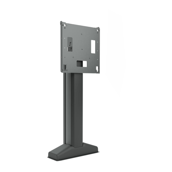
Electrical Height Adjustable Video Stand
Istruzioni di installazione
Installatie-instructies
Instructions d´installation
Spanish Product Description
German Product Description
Portuguese Product Description
Italian Product Description
Dutch Product Description
French Product Description
LFE1U
Advertisement
Table of Contents

Related Manuals for LEGRAND Chief LFE1U


Summary of Contents for LEGRAND Chief LFE1U
- Page 1 I N S T A L L A T I O N I N S T R U C T I O N S Instrucciones de instalación Istruzioni di installazione Installationsanleitung Installatie-instructies Instruções de Instalação Instructions d´installation Electrical Height Adjustable Video Stand Spanish Product Description German Product Description Portuguese Product Description...
-
Page 2: Important Safety Instructions
TO REDUCE THE RISK OF product. The information contained in this document is subject BURNS, FIRE, ELECTRIC SHOCK, OR INJURY TO to change without notice or obligation of any kind. Legrand PERSONS: makes no representation of warranty, expressed or implied, regarding the information contained herein. - Page 3 A double-insulated product is marked Responsible Party: with the symbol (square within a square) Legrand | AV 6436 City West Parkway Eden Prairie, MN 55344 866-977-3901 av.support@legrand.com Electrical Specifications...
- Page 4 LFE1U Installation Instructions DIMENSIONS 16.25 412.8 TILT 4.01 101.8 18.75 476.3 4.00 101.6 1.50 38.1 2X 0.75 19.1 2.5 ROLL 2X 1.00 0.332 25.4 DETAIL B SCALE 1 : 5 DETAIL C SCALE 1 : 4 OPTIONAL ANCHOR HOLE FOR 1/4" SCREW 0.27 FRONT 0.38...
- Page 5 Installation Instructions LFE1U LEGEND Tighten Fastener Pencil Mark Apretar elemento de fijación Marcar con lápiz Befestigungsteil festziehen Stiftmarkierung Apertar fixador Marcar com lápis Serrare il fissaggio Segno a matita Bevestiging vastdraaien Potloodmerkteken Serrez les fixations Marquage au crayon Loosen Fastener Drill Hole Aflojar elemento de fijación Perforar...
-
Page 6: Tools Required For Installation
LFE1U Installation Instructions TOOLS REQUIRED FOR INSTALLATION 7/32" (5.3mm) - wood studs 3/8" (10mm) - concrete 1/2" (12.7mm) - steel/wood studs 1/8” (included) 3/16” (included) 1/2" PARTS Box "A" A2 (1) A1 (1) [Lower cover] C (1) [Bottom back cover] [Floor plate] Box "B"... - Page 7 LFE1U Installation Instructions PARTS - DISPLAY INTERFACE Hardware Kit Bag C Bag A Bag B WB (4) WC (4) WA (4) M4 x 12mm M4 x 25mm M4 x 20mm Bag D Bag F Bag E WF (4) WD (4) WE (4) M5 x 25mm M5 x 12mm...
-
Page 8: Assembly And Installation
LFE1U Installation Instructions Assembly And Installation Remove stand from box by tipping it from the top onto the floor plate. (See Figure 3) IMPORTANT ! : The LFE1U packaging was designed to help make the installation and setup easier. Do NOT remove assembly prior to reading installation instructions! Cart Assembly... - Page 9 Installation Instructions LFE1U Remove back cover to expose control box. (See Figure 6) 13. Plug in power cable (V) to control box and route along side of control box. Provide strain relief using the cable ties (K) 10. Route control pad cable (D) behind bottom back cover (A1) and cable clips.
- Page 10 LFE1U Installation Instructions 17. Attach display and signal cables to power source. Use cable Drill two 1/2" holes on marked hole locations NOT on stud. ties (K) to route as necessary. (See Figure 10) (See Figure 11) IMPORTANT ! : Do not install display at this time, only route the cables through the back cover.
- Page 11 Installation Instructions LFE1U Drywall (M) x 2 Plastic Cap (Q) x 2 Anchor Metal Channel SIDE VIEW Figure 13 10. Snap off plastic straps on anchor at wall by pushing side to (N) x 2 side, snapping off straps level with flange of plastic cap. (See Figure 14) Figure 15 Drywall...
- Page 12 LFE1U Installation Instructions Site Requirements (Steel Studs) 16" (on center) Studs LFE1U Installation Location If back side of wall is unfinished, drywall must be installed to a minimum of one stud left and right of the studs being used to install the mount. Drywall must be secured to studs with screws 12"...
- Page 13 Installation Instructions LFE1U Measure 5 5/8" off the finished floor to mark lower mounting locations and 32 5/8" off the finished floor for upper Steel Stud mounting locations with one of the locations being centered on stud. Holes must be 4" apart horizontally. (See Figure Drywall Mark hole locations at each mounting location.
- Page 14 LFE1U Installation Instructions Installing to a Concrete Wall 10. Place wall brackets (B1) over anchors and align mounting slots on mount with holes in anchors. (See Figure 21) Measure 5 5/8" off the finished floor to mark lower mounting 11. Install four 5/16-18 x 3 3/4" Phillips pan machine screws (M) locations and 32 5/8"...
-
Page 15: Display Installation
Installation Instructions LFE1U Install four 5/16 x 1/2” button head cap screws (X) through Determine and mark the vertical center position between slots on wall brackets (B1) and side of column assembly (P). the Right side Upper and Lower mounting holes in display. (See Figure 25) (See Figure 26) (TR) x 2... - Page 16 LFE1U Installation Instructions (WMA) x 4 (WMB) x 4 (WR) (WA through WL) (WR) x 2 Figure 28 If the display has a recessed mounting surface, protrusions or a power box, a spacer and longer mounting hardware must be placed between the display and vertical mounting bracket (WR).
-
Page 17: Height Adjustment
Installation Instructions LFE1U (WR) x 2 (WR) x 2 (WN) x 8 (WQ) x 2 Figure 30 18. Make sure latching flags are in "closed" position prior to using cart! IMPORTANT ! : Manufacturer recommends using cable ties (K) to secure the latching flags in closed position on "PRESETS"... -
Page 18: Troubleshooting
LFE1U Installation Instructions Tilt Adjustment IMPORTANT ! : Remove display from mount prior to (rear view) adjusting tilt! Use 3/16" hex key (H) to remove tilt adjustment screws on both sides. (See Figure 33) Adjust faceplate tilt and re-install removed screw in either the middle hole for 2°... - Page 19 Installation Instructions LFE1U...
-
Page 20: Installation Instructions
P +31 (0) 495 580 852 F +31 (0) 495 580 845 Asia Pacific A Office No. 918 on 9/F, Shatin Galleria 8800-003128 Rev00 18-24 Shan Mei Street 2019 Legrand Fotan, Shatin, Hong Kong www.legrandav.com P 852 2145 4099 06/19 F 852 2145 4477...
Need help?
Do you have a question about the Chief LFE1U and is the answer not in the manual?
Questions and answers