Siemens SIMATIC ET 200SP Manual
Analog output module aq 4xi hart hf (6es7135-6td00-0ca1)
Hide thumbs
Also See for SIMATIC ET 200SP:
- System manual (409 pages) ,
- Manual (270 pages) ,
- Operating instructions manual (166 pages)

Related Manuals for Siemens SIMATIC ET 200SP


Summary of Contents for Siemens SIMATIC ET 200SP
- Page 1 SIMATIC ET 200SP Analog output module AQ 4xI HART HF (6ES7135-6TD00-0CA1) Manual Edition 11/2018 Answers for industry.
- Page 3 Preface Documentation guide Product overview SIMATIC Wiring up ET 200SP Analog Output Module AQ 4xI HART HART function Parameters Manual Configuring/address space Interrupts/diagnostics alarms Technical specifications Appendix 05/2019 A5E35098013-AA...
- Page 4 Note the following: WARNING Siemens products may only be used for the applications described in the catalog and in the relevant technical documentation. If products and components from other manufacturers are used, these must be recommended or approved by Siemens. Proper transport, storage, installation, assembly, commissioning, operation and maintenance are required to ensure that the products operate safely and without any problems.
-
Page 5: Preface
In order to protect plants, systems, machines and networks against cyber threats, it is necessary to implement – and continuously maintain – a holistic, state-of-the-art industrial security concept. Siemens’ products and solutions constitute one element of such a concept. Customers are responsible for preventing unauthorized access to their plants, systems, machines and networks. - Page 6 Siemens’ products and solutions undergo continuous development to make them more secure. Siemens strongly recommends that product updates are applied as soon as they are available and that the latest product versions are used. Use of product versions that are no longer supported, and failure to apply the latest updates may increase customer’s exposure to cyber...
-
Page 7: Table Of Contents
Table of contents Preface .................................3 Documentation guide ...........................7 Product overview ............................9 Properties ..........................9 Wiring up ..............................11 Connection and block diagram....................11 HART function ............................15 How HART works........................16 Use of HART ..........................20 HART communication interface .....................22 HART variables ........................24 Parameters ..............................27 Parameters of AQ 4xI HART....................27 5.1.1 Channel/technology parameters ....................27 5.1.2... - Page 8 Table of contents HART operating data records ....................57 A.2.1 HART directory........................57 A.2.2 HART feature data .........................58 A.2.3 HART variable data record.....................58 A.2.4 HART-specific settings......................59 A.2.5 HART request and response data records................60 A.2.6 Example of HART programming (HART command interface) ..........63 Analog value display ......................66 A.3.1 Analog value display in the current output range 0 to 20 mA..........66...
-
Page 9: Documentation Guide
BaseUnits Manual ET 200SP BaseUnits (http:// Technical specifications support.automation.siemens.com/ WW/view/en/59753521) SIMATIC manuals The latest manuals for SIMATIC products are available for download free of charge from the Internet (http://www.siemens.com/simatic-tech-doku-portal). Analog Output Module AQ 4xI HART HF Manual, 05/2019, A5E35098013-AA... - Page 10 Documentation guide Analog Output Module AQ 4xI HART HF Manual, 05/2019, A5E35098013-AA...
-
Page 11: Product Overview
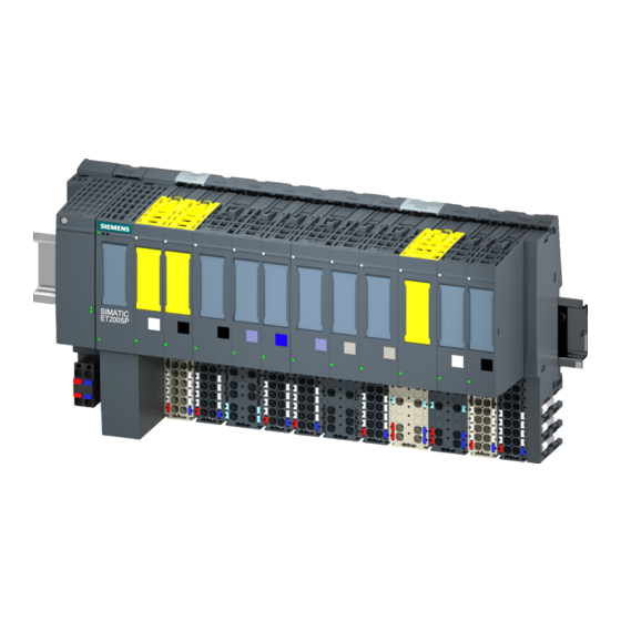
Product overview Properties Article number 6ES7135-6TD00-0CA1 View of the module Figure 2-1 View of the AQ 4xI HART HF module Properties The module has the following technical properties: ● Analog output module with 4 outputs ● Current output in output ranges 0 to 20 mA, 4 to 20 mA and 4 to 20 mA HART ●... - Page 12 ● Color identification labels ● Reference identification label ● Shield connector See also You will find additional information on the accessories in the ET 200SP distributed I/O system (https://support.industry.siemens.com/cs/ww/en/view/91696622) system manual. Analog Output Module AQ 4xI HART HF Manual, 05/2019, A5E35098013-AA...
-
Page 13: Wiring Up
You can find an overview of the BaseUnits that you can use with the analog module in Product information for documentation of the ET 200SP Distributed I/O System (http:// support.automation.siemens.com/WW/view/en/73021864) You can find information regarding selection of the suitable BaseUnit in system manual ET 200SP distributed I/O system (http://support.automation.siemens.com/WW/view/en/... - Page 14 Wiring up 3.1 Connection and block diagram General terminal assignment ① Optional connection of an external hand‐ held unit (secondary master) to the HART test connection terminals (at channel 0 in this case) ② Connecting an actuator with 4...20 mA in‐ terface, with or without HART ③...
- Page 15 Wiring up 3.1 Connection and block diagram Supply voltage L+/M Connect supply voltage (24V DC) to terminals L+ and M. An internal protective circuit protects the analog module from reverse polarity. The analog module monitors the connection of the supply voltage. Analog Output Module AQ 4xI HART HF Manual, 05/2019, A5E35098013-AA...
- Page 16 Wiring up 3.1 Connection and block diagram Analog Output Module AQ 4xI HART HF Manual, 05/2019, A5E35098013-AA...
-
Page 17: Hart Function
HART function Definition "HART" stands for "Highway Addressable Remote Transducer". The HART protocol is a standardized communication protocol for communication with the suitable field devices over a bus system. HART is a registered trademark of the HART Communication Foundation (HCF), which owns all the rights to the HART protocol. -
Page 18: How Hart Works
HART function 4.1 How HART works How HART works Introduction The HART protocol describes the physical form of the transfer: transfer procedures, message structure, data formats and commands. HART signal The figure below shows the analog signal with the modulated HART signal (FSK method), which consists of sine waves of 1200 Hz and 2200 Hz and has a mean value of 0. - Page 19 HART function 4.1 How HART works If a HART field device with a different short frame address is connected or a connected field device is reconfigured to a short frame address other than 0 during operation, the module starts a scan of all possible short frame addresses at the next re-establishment of HART communication (command 0 with short frame addresses 1...63).
- Page 20 HART function 4.1 How HART works Structure of the HART protocol Each HART frame sent from the analog module to the connected field device (request frame) and each HART frame from the field device (response frame) has the following basic structure. Table 4-3 Structure of the HART protocol PREAMBLE...
- Page 21 HART function 4.1 How HART works Table 4-5 2nd status byte Bit 7 = 1 Device fault Bit 6 = 1 Configuration changed Bit 5 = 1 Startup (cold start) Bit 4 = 1 Additional status information available Bit 3 = 1 Fixed analog output current setting Bit 2 = 1 Analog output current saturated...
-
Page 22: Use Of Hart
HART function 4.2 Use of HART Use of HART System environment for the use of HART To use an intelligent field device with HART functionality, you require the following system environment: ● Current loop 4 to 20 mA Connection of the field device to the analog module AQ 4xI HART ●... - Page 23 HART function 4.2 Use of HART Error management The two HART status bytes (HART device status) that are transferred with each field device response contain error statements about HART communication, HART command and device status. These statements are evaluated by the analog module and provided in the system via S7 diagnostics messages.
-
Page 24: Hart Communication Interface
HART function 4.3 HART communication interface HART communication interface Data records The HART commands are sent over data records to the connected field device as "external HART jobs" from the client (e.g. PDM or the STEP 7 user program). The response of the field device is made available again in the system via data records. - Page 25 HART function 4.3 HART communication interface Each request is stored on a channel-specific basis, and the corresponding request data record is disabled. Another writing of the same request data record is thus not possible and is acknowledged with BUSY. The disable of the request data record is reset after the termination or completion of the requested HART command.
-
Page 26: Hart Variables
HART function 4.4 HART variables HART variables Introduction Numerous HART field devices make available additional measured quantities (e.g. sensor temperature). A maximum of four HART variables supported by the connected field device can be cyclically read per channel with activated HART functionality. The HART variables are read automatically with HART command 3 (for field devices with HART rev. - Page 27 HART function 4.4 HART variables Basic structure of the quality code 7...6 5...2 1…0 Quality Sub-status Limits 0 0: Bad Coded according to "PROFIBUS PA Profile for 0 0: OK 0 1: Uncertain Process Control Devices" 0 1: Low limit 1 0: Good 1 0: High limit 1 1: Good...
- Page 28 HART function 4.4 HART variables Field devices with HART Revision 7 or higher The quality code is formed from the 1st status byte (HART device status) and the "Device variable status" (DVS) of the response frames (HART command 9). Quality code Meaning (process status) Note Value is okay...
-
Page 29: Parameters
Parameters Parameters of AQ 4xI HART You define the functioning of the Q 4xI HART analog module via parameters. The parameters are subdivided into: ● Channel/ technology parameters (data record 128) With PROFIBUS DP GSD configuration, there is a reduced configuration via the startup configuration (Prm frame). - Page 30 Parameters 5.1 Parameters of AQ 4xI HART Parameter Value range Default Configura‐ Effective range with configura‐ tion in RUN tion software, e.g. STEP 7 (TIA Portal) GSD file PRO‐ GSD file FINET IO PROFIBUS Diagnostics, Disable Channel Module ● Disable Short-circuit ●...
-
Page 31: Explanation Of The Channel/Technology Parameters
Parameters 5.1 Parameters of AQ 4xI HART See also Parameter assignment and structure of the channel/technology parameters (Page 53) 5.1.2 Explanation of the channel/technology parameters Output type/range The analog module has the following output ranges: Table 5-2 Output range Type of output Output range Resolution Disabled... - Page 32 Parameters 5.1 Parameters of AQ 4xI HART Figure 5-2 Example diagram of settling time with HART communication Diagnostics no supply voltage L+ Enabling of the diagnostics for no or insufficient supply voltage L+. Diagnostics, Wire break Enabling of the diagnostics if the analog module does not detect any current flow. Monitoring is effective from an output current of ≥...
- Page 33 Parameters 5.1 Parameters of AQ 4xI HART Diagnostics underflow Enable diagnostics. ● The event is signaled when the output value violates the underrange. Diagnostics HART Enable the following diagnostics: ● HART frame-specific monitoring ● Status information provided by the connected field device in the HART frame (HART device status).
-
Page 34: Hart Mapping Parameters
5.1 Parameters of AQ 4xI HART Potential group Specifies that a BaseUnit with supply voltage infeed is located in this slot (see system manual ET 200SP Distributed I/O System (http://support.automation.siemens.com/WW/view/en/ 58649293)). 5.1.3 HART mapping parameters A maximum of 4 HART variables can be configured (mapped) to the address space of the module with the HART mapping parameters. - Page 35 Parameters 5.1 Parameters of AQ 4xI HART Parameter Value range Default Configuration in With GSD file PRO‐ FIBUS DP Variable Chan‐ 0…3 Type Non / Cir Secondary ● Non / Cir ● Primary ● Secondary ● Tertiary ● Quaternary Variable Chan‐...
- Page 36 Parameters 5.1 Parameters of AQ 4xI HART Analog Output Module AQ 4xI HART HF Manual, 05/2019, A5E35098013-AA...
-
Page 37: Configuring/Address Space
● With STEP 7 V5.6 + SP4 or higher (HSP0263) ● Using GSD/GSDML The GSD files for the ET 200SP Distributed I/O System can be downloaded from the Internet: GSDML (http://support.automation.siemens.com/WW/view/en/57138621) GSD (http://support.automation.siemens.com/WW/view/en/73016883) Configuration options The following configurations are possible: ●... -
Page 38: Address Space
Configuring/address space 6.2 Address space Address space The following tables shows the mapping of the address space of the AQ 4xI HART analog output module for a configuration with value status (Quality Information, QI) and with HART variables. Abbreviations ● "IB" stands for input byte, that is, the module start address in the input area ●... - Page 39 Configuring/address space 6.2 Address space Each HART variable consists of a 4-byte real value and a quality code byte. The quality code describes the validity of the value; see section HART variables (Page 24) . The assigned HART variables are automatically updated by the I/O module and can be used directly in the user program.
- Page 40 Configuring/address space 6.2 Address space Analog Output Module AQ 4xI HART HF Manual, 05/2019, A5E35098013-AA...
-
Page 41: Interrupts/Diagnostics Alarms
Interrupts/diagnostics alarms Status and error displays LED displays The following figure shows the status and error displays of the AQ 4xI HART analog output module. ① DIAG (green/red) ② Channel status (green) ③ Channel fault (red) ④ PWR (green) Figure 7-1 LED displays Meaning of the LED displays The following tables show the meaning of the status and error displays. - Page 42 Interrupts/diagnostics alarms 7.1 Status and error displays LEDs Meaning Channel Channel status fault Channel enabled and channel diagnostics present Channel enabled and only HART channel diagnostics present Table 7-2 DIAG LED error display DIAG LED Meaning Backplane bus supply of the ET 200SP is not OK or switched off Module parameters not assigned Flashes Module parameters assigned and no module diagnostics...
-
Page 43: Interrupts
Interrupts/diagnostics alarms 7.2 Interrupts Interrupts The AQ 4xI HART analog output module supports diagnostic interrupts. Diagnostic interrupt The module generates a diagnostic interrupt for the following events: ● Channel/component temporarily unavailable ● Short-circuit ● Wire break ● Low limit violated ●... -
Page 44: Diagnostics Alarms
Interrupts/diagnostics alarms 7.3 Diagnostics alarms Diagnostics alarms A diagnostic alarm is generated for each detected diagnostic event. The DIAG LED flashes on the module. There is additionally a channel-specific display of the diagnostics through the corresponding channel fault/channel status LEDs. The diagnostic alarms can, for example, be read from the diagnostic buffer of the CPU or be displayed in STEP 7 using the Online and Diagnostics view. - Page 45 Interrupts/diagnostics alarms 7.3 Diagnostics alarms Diagnostic alarm Error code Meaning Remedy HART primary variable ● Incorrect parameters in the HART field ● Check the parameter assignment of outside range device the HART device ● HART field device is set to "Primary ●...
- Page 46 Interrupts/diagnostics alarms 7.3 Diagnostics alarms Analog Output Module AQ 4xI HART HF Manual, 05/2019, A5E35098013-AA...
-
Page 47: Technical Specifications
Technical specifications Technical specifications of the AQ 4xI HART Technical specifications Article number 6ES7135-6TD00-0CA1 General information Product type designation AQ 4xI HART HF Firmware version V1.0 ● FW update possible usable BaseUnits BU type A0, A1 Color code for module-specific color identifica‐ CC00 tion plate Product function... - Page 48 Technical specifications 8.1 Technical specifications of the AQ 4xI HART Article number 6ES7135-6TD00-0CA1 Number of analog outputs Current output, no-load voltage, max. 28 V Cycle time (all channels), min. 3 ms Output ranges, current Yes; 16 bit incl. sign ● 0 to 20 mA ●...
- Page 49 50 °C ● vertical installation, max. Dimensions Width 15 mm Height 73 mm Depth 58 mm Weights Weight, approx. 31 g Dimension drawing See manual ET 200SP BaseUnits (http://support.automation.siemens.com/WW/view/en/ 59753521) Analog Output Module AQ 4xI HART HF Manual, 05/2019, A5E35098013-AA...
-
Page 50: Standards And Approvals
Technical specifications 8.2 Standards and Approvals Standards and Approvals 8.2.1 Currently valid markings and approvals Introduction This section contains the technical specifications of the system: ● The standards and test values that the module complies with and fulfills. ● The test criteria according to which the module was tested. Safety information WARNING Explosion hazard... - Page 51 Technical specifications 8.2 Standards and Approvals WARNING Enclosure and cables The device is intended for installation in an enclosure / control cabinet. The internal operating temperature of the enclosure / control cabinet corresponds to the maximum permissible ambient temperature of the module. Cables must be used whose maximum permissible operating temperature is at least 30 °C above the maximum permissible ambient temperature.
-
Page 52: Atex Approval
Technical specifications 8.2 Standards and Approvals NOTICE Risk of danger Read the manual before use to avoid injury. Validity of the information on the components NOTICE Markings and approvals In the documentation, you can find the markings and approvals which are generally possible or planned in the system. -
Page 53: Iecex Approval
Technical specifications 8.2 Standards and Approvals 8.2.3 IECEx Approval Table 8-2 IECEx certification Certificate number IECEx DEK 14.0063X Standards IEC 60079-0 IEC 60079-7 IECEx Ex ec IIC T4 Gc Note Special conditions 1. The module may only be used in areas with a pollution degree of not more than 2 according to IEC 60664‑1. - Page 54 Technical specifications 8.2 Standards and Approvals Analog Output Module AQ 4xI HART HF Manual, 05/2019, A5E35098013-AA...
-
Page 55: Appendix
Appendix Parameter data records Parameter assignment in the user program You have the option of reassigning parameters for individual channels of the module and for the mapping of HART variables in RUN without affecting the other channels. Changing parameters in RUN The "WRREC"... - Page 56 Appendix A.1 Parameter data records The parameters are divided into parameters which influence the actual analog value output, diagnostic enables and basic parameters of the HART communication. You can use data records 131 to 134 to assign and change additional parameters and HART- specific settings.
-
Page 57: Parameter Assignment And Structure Of The Hart Mapping Parameters
Appendix A.1 Parameter data records x = 2 + (channel number * 8); with channel number 0….3 Figure A-3 Structure byte x to x+33 for channels 0 to 3 A.1.2 Parameter assignment and structure of the HART mapping parameters Structure of data record 140 Data record 140 has a total length of 12 bytes. - Page 58 Appendix A.1 Parameter data records Header information The figure below shows the structure of the header information. Figure A-4 Header information Parameters The following figure shows the parameter assignment of the four HART variables 0...3. * x = 4 + (HART variable * 2); with HART variable 0….3 Figure A-5 Parameters Note...
-
Page 59: Hart Operating Data Records
Appendix A.2 HART operating data records HART operating data records Reading/writing data in RUN HART operating data records are transferred to the module with the "WRREC" instruction and read from the module with the "RDREC" instruction. Errors during the transfer are indicated at output parameter STATUS of the "WRREC" or "RDREC". -
Page 60: Hart Feature Data
Appendix A.2 HART operating data records Byte Meaning Comment Index of HMD Module Parameter = 255 (not relevant) Start Index of Burst Buffer Area = 255 (not relevant) Index of HMD Channel Parameter (Channel = 131+n 9+n+4 Index of HART Client Channel Message = 80+(2*n) Data The HART request data records cannot be... -
Page 61: Hart-Specific Settings
Appendix A.2 HART operating data records Byte Meaning 15…18 Value Quartenary (QV) Quality code Channel 1 20…39 HART variables same as for Channel 0 Channel 2 40…59 HART variables same as for Channel 0 Channel 3 60…79 HART variables same as for Channel 0 If HART is not enabled or the respective HART variable is not supplied from the connected field device, the corresponding variable = 0 and the QC = 0x37 (initialization value from the analog module). -
Page 62: Hart Request And Response Data Records
Appendix A.2 HART operating data records Structure of the HART-specific settings Figure A-6 Settings * When the number of HART preamble bytes = 0, the number of preamble bytes required by the connected field device are used, but no fewer than 5. When the number of HART preamble bytes = 255, then 20 preamble bytes are used. - Page 63 Appendix A.2 HART operating data records Structure of request data records 80, 82, 84, 86 Byte Meaning Comment Request control Coding "Request control": Bit 0… Reserved = 0 Bit 2: 0 = Parameters are not checked Reserved = 0 3...4: Bit 5: ●...
- Page 64 Appendix A.2 HART operating data records In case of response error Byte Meaning Comment Response control See table below: Coding "Response control": HART group error display See table below: Coding "HART group error display" 2…239 Response data according to HART speci‐ Only present when "Response result"...
-
Page 65: Example Of Hart Programming (Hart Command Interface)
Appendix A.2 HART operating data records Coding "HART protocol error during response" HART proto‐ Meaning Explanation col error dur‐ ing response Unspecified error Always 0 HMD error 0: Not specified 4: Wait time expired 1: Internal communication error 5: HART timer expired 2: Parameter assignment error 6…127: Reserved 3: HW fault... - Page 66 Appendix A.2 HART operating data records U E 4.0 FP M 101.0 = M 104.0 m2: CALL SFC 58 REQ :=M104.0 IOID :=B#16#54 LADDR :=W#16#200 RECNUM :=B#16#50 RECORD :=P#DB80.DBX0.0 BYTE 11 RET _ VAL :=MW93 BUSY :=M51.0 A M 51.0 SPB m2 Table A-1 DB80: Transparent message format...
- Page 67 Appendix A.2 HART operating data records You can learn when the response from the field device was received by cyclically reading data record DS81 for HART channel 0. The response is always supplied in transparent message format. FC81: Reading of the response to DB81 with SFC 59 m3: CALL SFC 59 REQ :=1 IOID :=B#16#54...
-
Page 68: Analog Value Display
Appendix A.3 Analog value display Analog value display In the following tables, you can find the digitized representation of the unipolar output ranges. Display of analog value of current output ranges: ● Analog value display in the current output range 0 to 20 mA (Page 66) ●... - Page 69 Appendix A.3 Analog value display Values Current output range Range 106.25% 29376 72C0 21 mA Overrange 27649 6C01 20 mA + 578.7 nA 100% 27648 6C00 20 mA Nominal range 20736 5100 16 mA 0.003617% 4 mA + 578.7 nA 4 mA FFFF 4 mA –...
-
Page 70: Contact
Appendix A.4 Contact Contact Range Contact Repair Service Fa‐ Siemens AG cility Digital Industries Factory Automation Operative Q functions DI FA MF EWA QM 31 Mr. Alexander Luber Werner-von-Siemens-Str. 5092224 Amberg, Germany Tel.: +49 9621 80-3447 Manufacturer Siemens AG Digital Industries... -
Page 71: Index
Index Address assignment, 24 Data record 128, 53 Address space, 36 Header information, 54 Approval Parameters, 54 ATEX, 50 Data record 140, 55 IECEx, 51 Header information, 56 Approvals, 50 Parameters, 56 AQ 4xI HART Data records, 22 Accessories, 10 Device status, 18 Address space, 36 DIAG LED, 40... - Page 72 Index Operating data records, 57 Parameter assignment tool, 20 Principle of operation, 16 Programming, 63 SHC sequence, 23 Protocol, 15, 18 SIMATIC PDM configuration tool, 20 Settings, 60 Standards, 50 Signal, 16 Status indications, 39 System environment, 20 Supply voltage, 13 Variable data record, 58 System environment, 20 Variables, 24...
Need help?
Do you have a question about the SIMATIC ET 200SP and is the answer not in the manual?
Questions and answers