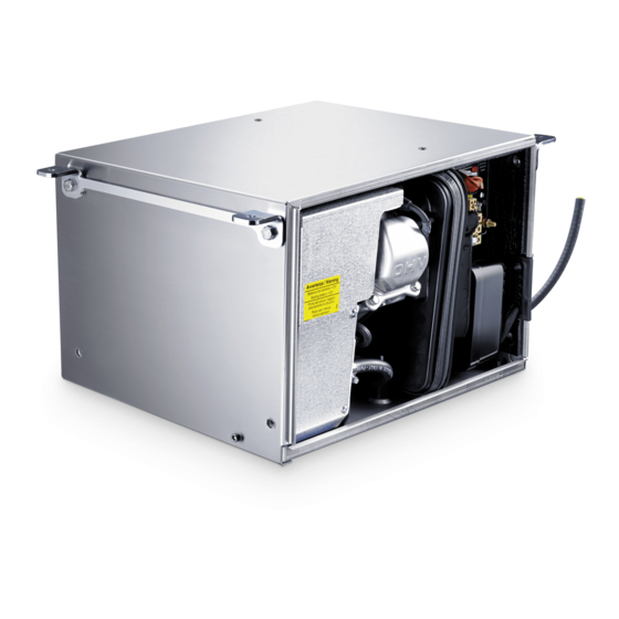
Dometic TEC 29 User Manual
Hide thumbs
Also See for TEC 29:
- Operating manual (404 pages) ,
- Installation manual (304 pages) ,
- Installation manual (300 pages)
Table of Contents
Advertisement
©DOMETIC - 2006 All rights reserved - Printed in Italy -
No part of this manual may be reproduced, copied or transmitted in
any form or by any means without prior written permission from
DOMETIC.
Figures, descriptions, references and technical data contained in this
manual are given as mere example and are not binding.
In pursuing a policy of constant product and safety improvement,
DOMETIC reserves the right to effect changes at any time without
undertaking to give prior notice or to update this manual every time.
Keep this document for future reference.
Advertisement
Table of Contents

Related Manuals for Dometic TEC 29


Summary of Contents for Dometic TEC 29
- Page 1 ©DOMETIC - 2006 All rights reserved - Printed in Italy - No part of this manual may be reproduced, copied or transmitted in any form or by any means without prior written permission from DOMETIC. Figures, descriptions, references and technical data contained in this manual are given as mere example and are not binding.
- Page 2 The Manufacturer’s warranty does not extend to Product failures, defects or damage arising from and/or attributable to a wrong installation. The Consumer is entitled to let the Product be installed by an authorised dealer, not bound by Dometic. The warranty extends to failures or defects in the gen-sets which shall become apparent within the warranty period.
-
Page 3: Table Of Contents
Brukerveiledning og manual TEC 29 wiring diagram............24 til vedlikehold og installasjon Generator TEC 29 wiring diagram - 2 TEC 29 in parallel mode....25 TEC 29 spare parts table............. 26 Brugervejledning og manual AG102 wiring diagram............28 til vedligeholdelse og installation... -
Page 4: Purpose Of The Manual
Information on the protection of the environment. Manufacturer’s data Manufactured by v.Virgilio,3 Forlì-Italy Conformity marking PRODUCT No. MODEL SERIAL Model/Serial number xxxxxxxx 958 500 213 TEC 29 Year of manufacture Date 2002 Voltage V230 Output max W2900 Technical data Frequency Hz 50... -
Page 5: Safety
General information 1 • The company Dometic is not responsible for any damage caused by Exhaust gases contain carbon monoxide, an extremely poisonous generator malfunctions. gas, which is odourless and colourless. Avoid inhaling exhaust gases. Do not run the engine of the generator in a closed garage 1.3 Safety... -
Page 6: Description Of The Generator
1.5 Description of the generator 1.7 Operation description Warning The main elements of the TEC 29 generator are: an engine (a), a The TEC 29 generator has been designed and produced to be used permanent magnet alternator (b), an inverter (c), an internal control only on caravans, motor homes and commercial vehicles. - Page 7 General information 1 INVERTER CONTROL MAGNET CARD STEP MOTOR ENGINE (A) TERMINAL BOARD (E) INTERNAL CONTROL PANEL EXTERNAL CONTROL PANEL ALTERNATOR UNIT user’s manual TEC 29...
-
Page 8: External Control Panel
OIL INDICATOR: indicates a low oil level in the engine EMERGENCY STOP SWITCH: stops the generator immediately in an emergency CUT OUT SWITCH: continuous current thermal cut out protection user’s manual TEC 29... -
Page 9: Technical Data
1.10 Technical data V V V V V ± ± ± ± ± W W W W W ± ± ± ± ± ± ± ± ± ± % % % % % 1 1 1 1 1 user’s manual TEC 29... -
Page 10: Display Messages
1 General information 1.11 Table describing the alarm messages appearing on the display l l i “ . ” user’s manual TEC 29... -
Page 11: Routine Maintenance
Perform all of the checks making sure the generator is in a horizontal standard are used. position. IMPORTANT: Remember to reconnect the positive pole (+) of the vehicle’s battery and set the switch back to “I” (ON) once you have finished the checks. user’s manual TEC 29... -
Page 12: Installation Instructions
The air intake must be at least 240 cm . Furthermore you should also install a fire-proof rubber gasket of at least 5mm between the floor and the base of the generator (available as accessory Ref. AG128). user’s manual TEC 29... -
Page 13: Instructions For Installing The Exhaust Terminal
Use the exhaust extension (available as accessory Ref. AG125) to extend the position of the muffler. Fix the extension to the floor of the vehicle. WARNING Do not make any sharp bends in the hose which could obstruct the exhaust gas. EXHAUST EXTENSION EXTENSION MUFFLER FIXING AG125 TEC 29 EXHAUST ELBOW user’s manual TEC 29... - Page 14 2 Installation instructions Instructions for installing the exhaust system user’s manual TEC 29...
- Page 15 Installation instructions 2 Instructions for installing the exhaust system user’s manual TEC 29...
-
Page 16: Instructions For Installing The Fuel Tank
The fuel tank should be installed with the tank basis at a maximum depth of 0.3 meters below the lower edge of the generator box. For safety reasons ensure not to mount the generator box top edge higher than the tank top edge. user’s manual TEC 29... -
Page 17: Instructions For The Electrical Connection
(See picture on page 18) 12 V plug for battery charger Cut out switch 230 V Earth wire plug (+) plus pole user’s manual TEC 29... - Page 18 To protect the DC wiring use a 100Amp fuse closed to the plus pole of the battery. External control panel connection Choose the desired position inside the vehicle, use the extension lead (supplied) to connect the external control panel to the internal control panel of the generator. Inserts user’s manual TEC 29...
-
Page 19: Troubleshooting, Maintenance, Recycling 3
The starting motor runs but the generator does not start The generator tends to stall The generator runs but it does not produce current The generator starts, then stops and display “generator allert” message The produced current oscillates user’s manual TEC 29... -
Page 20: Checks - Nature And Service Intervals
3 Troubleshooting, maintenance, recycling 3.2 Check list and time intervals r i f t n i r i f l i o t l i f t l i f x i f n i l user’s manual TEC 29... -
Page 21: Extraordinary Maintenance
Refill the generator with oil of the recommended type, through the oil filler. The quantity of oil is: 0.6 Litres user’s manual TEC 29... - Page 22 Therefore, to prevent carburettor malfunctions we recommend checking the state of the filter periodically, and more often if you are using the TEC 29 in particularly dusty areas. Never use the engine without the air filter. The engine would wear quickly.
- Page 23 Once you have screwed the spark plug in by hand, tighten it with a plug wrench to compress the washer. user’s manual TEC 29...
-
Page 24: Tec 29 Wiring Diagram
TEC 29 WIRING DIAGRAM CYAN DESCRIPTION CYAN CYAN THREE-PHASE COIL BROWN BROWN AUXILIARY COIL AUXILIARY COIL INVERTER MODULE 11 10 9-PIN CONNECTOR WHITE 12V REGULATOR WHITE STEP MOTOR BLACK WHITE 4-PIN CONNECTOR BLACK WHITE START RELAY STARTING MOTOR CHOKE MAGNET... -
Page 25: Tec 29 Wiring Diagram - 2 Tec 29 In Parallel Mode
For parallel connection of 2 TEC29 follow the diagram in the picture . LOAD AG 113 (Accessory sold upon request) 2.5 mm MAINS TEC 29 2.5 mm 4 mm BATTERY 4 mm 4 mm TEC 29 2.5 mm Compulsorily: use change-over switch AG113 to protect the units against accidental connection to the main electric line... -
Page 26: Tec 29 Spare Parts Table
TEC 29 SPARE PARTS TABLE user’s manual TEC 29... - Page 27 TEC 29 SPARE PARTS TABLE Description STEP MOTOR FIXING PLATE GX 160 MOTOR SUPPORT.PLATE - INT. CONTROL PANEL STATOR FRONT PLATE - INTERNAL CONTROL PANE ROTOR SPARK PLUG METAL FLAP GEN. / INVERTER CASING DOOR ALTERNATOR COVER SHAPED CABLE GUIDE...
-
Page 28: Ag102 Wiring Diagram
CENTRALINA UTILIZZI AG 102 AG 102 EXTERNAL INLET SOCKET EXTERNAL INLET SOCKET SPINA ESTERNA SPINA ESTERNA GENERATOR GENERATOR blue blue red - rosso red - rosso black - nero black - nero AG 111 AG 111 user’s manual TEC 29...
Need help?
Do you have a question about the TEC 29 and is the answer not in the manual?
Questions and answers