Table of Contents
Advertisement
Operating Instructions
EMGZ492.EIP
Dual-channel measuring amplifier for ETHERNET/IP
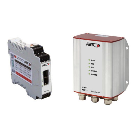
EMGZ492.R.EIP for mounting on DIN rail
EMGZ492.W.EIP for wall mounting
Document Version
1.0
09/2019 NS
Firmware Version
V 2.0.0
EDS Datei
FMS_TensionAmpilfier_EMGZ492_EIP_V1_1.eds
Diese Bedienungsanleitung ist auch in Deutsch erhältlich.
Bitte kontaktieren Sie Ihre lokale FMS Vertretung.
© by FMS Force Measuring Systems AG, CH-8154 Oberglatt – Alle Rechte vorbehalten.
Advertisement
Table of Contents

Subscribe to Our Youtube Channel
Related Manuals for FMS EMGZ492.EIP Series


Summary of Contents for FMS EMGZ492.EIP Series
- Page 1 EMGZ492.W.EIP for wall mounting Document Version 09/2019 NS Firmware Version V 2.0.0 EDS Datei FMS_TensionAmpilfier_EMGZ492_EIP_V1_1.eds Diese Bedienungsanleitung ist auch in Deutsch erhältlich. Bitte kontaktieren Sie Ihre lokale FMS Vertretung. © by FMS Force Measuring Systems AG, CH-8154 Oberglatt – Alle Rechte vorbehalten.
-
Page 2: Table Of Contents
Operating Instructions EMGZ492.EIP 1 Table of Contents TABLE OF CONTENTS ..........................2 SAFETY INFORMATION ........................... 4 Presentation of Safety Information ..................... 4 2.1.1 Danger that Could Result in Minor or Moderate Injuries ............... 4 2.1.2 Note Regarding Proper Function ....................4 General Safety Information ........................ - Page 3 Operating Instructions EMGZ492.EIP System Settings ..........................36 DIMENSIONS ............................37 TECHNICAL DATA ..........................38 09.09.2019...
-
Page 4: Safety Information
Operating Instructions EMGZ492.EIP 2 Safety Information All safety information, operating and installation regulations listed here ensure proper function of the device. Safe operation of the systems requires compliance at all times. Noncompliance with the safety information or using the device outside of the specified performance data can endanger the safety and health of persons. -
Page 5: General Safety Information
Operating Instructions EMGZ492.EIP 2.2 General Safety Information The function of the measuring amplifier is only ensured with the components in the specified layout to one another. Otherwise, severe malfunctions may occur. Thus, observe the mounting information on the following pages. Observe the local installation regulations. -
Page 6: Product Description
The measured force values are available via ETHERNET/IP and an analog voltage output. The measuring amplifiers are suitable for tension measurements using all FMS force sensors. Two force sensors A and B can be connected to the device. Both measuring values are available as individual signal (A and B), as sum signal (A + B), as differential signal |A –... - Page 7 Operating Instructions EMGZ492.EIP The following is not included in the scope of delivery, but are available as accessories from FMS Patch cable with RJ45 plug (straight or 90°) Sensor cable for the connection of force sensor and measuring amplifier M12 plug, D-coded...
-
Page 8: Quick Guide/Quick Start
Operating Instructions EMGZ492.EIP 4 Quick Guide/Quick Start In these operating instructions, commissioning of the EMGZ492.EIP amplifier is limited to the installation procedure, offset compensation, and system calibration. 4.1 Preparations for Parameterization Read the operating instructions of the selected force sensor carefully. Check your requirements on the system, such as: o Used units in the system o Used outputs (0 to 10V and bus) -
Page 9: Force Sensor Mounting
2x2x0.25 mm [AWG 23] shielded, twisted cable. 4.5.1 EMGZ492.R.EIP Figure 2: EMGZ492.R.EIP electrical connections EMGZ492_EIP_BA_Manual.ai Color specifications (per IEC60757) and coding apply to FMS components only! For easier installation, the terminal blocks can be detached from the main housing. 09.09.2019... -
Page 10: Emgz492.W.eip
Operating Instructions EMGZ492.EIP Figure 3: Detachable terminal blocks: use a small slotted screwdriver as a lever 4.5.2 EMGZ492.W.EIP The 4 screws of the cover with the PG glands and the M12 plug must be loosened for board access. You can slide out the board by approx. 2 cm (1 in.) and loosen the terminal blocks for easier connection of the wires. -
Page 11: Ethernet Anschlüsse
Operating Instructions EMGZ492.EIP 4.5.3 Ethernet Anschlüsse Tabelle 1: Pin Belegung Ethernet Anschluss EMGZ492_EIP_BA_Manual.ai Warning Poor grounding can result in electric shocks for persons, malfunctions of the overall system or damage to the measuring amplifier! Proper grounding must always be ensured. Note Cable shielding may only be connected to one side of the measuring amplifier. -
Page 12: Calibration Of The Measuring System
If the material tension in the machine cannot be replicated using the weight method (e.g., for space reasons), the gain can be calculated using the “FMS-Calculator”. This tool can be downloaded from the FMS homepage. Figure 6: Replication of the material profile using a defined weight Tension_Control_Solutions.ai... -
Page 13: Calibration
Operating Instructions EMGZ492.EIP 5.3 Calibration Activate the web interface (see 9) and click on “Offset/Calibration” from the menu (see 9.3). Connect the first force sensor (see 4.5). The measuring signal must become positive for loads in measuring direction. If it is negative, the signal lines of the affected force sensors must be switches at the terminal block (see 4.5). -
Page 14: Limit Value Violations
Test rule: The FMS force sensors deliver 9 mV at the output under nominal force load. In the case of a load up to the mechanical stop, approx. 12.4 mV are output. These values apply, if the force sensor is loaded in normal operating direction (red point). In reverse direction, the values are respectively negative. -
Page 15: Overflow And Underflow Test
Operating Instructions EMGZ492.EIP removed again, as soon as the raw value is 0.5 mV below and/or above the triggering limit value. 5.5.2 Overflow and Underflow Test The overflow and underflow test is performed with the output value that is relayed to the DAC, calculated from the gain. -
Page 16: Integration Into The Ethernet/Ip Network
Operating Instructions EMGZ492.EIP 6 Integration into the EtherNet/IP Network The measuring amplifiers of the EMGZ492.EIP series can operate in an EtherNet/IP network. Here, the amplifier operates as EtherNet/IP-adapter with the PLC which has the role of a EtherNet/IP-scanner. 6.1 EtherNet/IP Interface EtherNet/IP is supported. -
Page 17: Configuration
Operating Instructions EMGZ492.EIP 7 Configuration The EMGZ492.EIP can be configured either via the web interface or via ETHERNET/IP. The parameters “Low-pass filter active” and “Low-pass filter analog output active” cannot be accessed via the web interface. 7.1 Modify IP address with RLLinx 09.09.2019... - Page 18 Operating Instructions EMGZ492.EIP 09.09.2019...
-
Page 19: Parameter Description
Operating Instructions EMGZ492.EIP 7.2 Parameter Description Access data with RSLogix 5000 Parameter Name Description Unit Here you select which unit of measurement is used. The label located on the sensor will indicate the nominal force in Newtons. Note: This input will also affect the unit of the cyclic process data. - Page 20 Operating Instructions EMGZ492.EIP Low-pass filter active A Here, the status of the low-pass filter active value for the force sensor A is indicated. This parameter cannot be accessed via the web interface. Min. Max. Specified value 0 = no, inactive, 1 = yes, active Offset A The values determined with the “Offset Compensation”...
- Page 21 Operating Instructions EMGZ492.EIP Low-pass filter active B Here, the status of the low-pass filter active value for the force sensor B is indicated. This parameter cannot be accessed via the web interface. Min. Max. Specified value 0 = no, inactive, 1 = yes, active Offset B The values determined with the “Offset Compensation”...
-
Page 22: Cyclic Data Traffic
Operating Instructions EMGZ492.EIP Low-pass filter analog Here, the status of the low-pass filter for the analog output active output is indicated. This parameter cannot be accessed via the web interface. Min. Max. Specified value 0 = no, inactive, 1 = yes, active Limit frequency low- The amplifier features a low-pass filter that filters the pass filter analog... - Page 23 Operating Instructions EMGZ492.EIP Parameter Name Description Actual value A in ADC Value read in via the A/D converter. Data type int (signed 16 bit) Value range -16384 bis 16383 Value format ±##### The value is interpreted as integer without decimal place. E.g.
- Page 24 Operating Instructions EMGZ492.EIP Actual value B in ADC Value read in via the A/D converter. Data type int (signed 16 bit) Value range -16384 bis 16383 Value format ±##### The value is interpreted as integer without decimal place. E.g. 1000 = 1000 ADC raw value Actual value B in Filtered actual value converted into Newton Newton...
- Page 25 Operating Instructions EMGZ492.EIP Actual value A + B in Filtered actual values sum signal converted into unit configured unit. Data type long (signed 32 bit) Value range ±200‘000‘000 Value format ±#######.### for N, kN, kg, or lb The value is interpreted as decimal number with 3 decimal places.
-
Page 26: Acyclic Data Traffic
Operating Instructions EMGZ492.EIP Status The status contains information about the current process and operating condition. Every bit represents a separate event. The condition is active, if the bit is set. Data type byte (unsigned 8 bit) Bit 0 Overload (LSB) A Bit 1 Overload (LSB) B Bit 2... - Page 27 Operating Instructions EMGZ492.EIP Parameter Description 10241 Unit Access type Parameter command unit Data type byte (unsigned 8 bit) Value range 0 to 4 0=N; 1=kN; 2=lb; 3=g; 4=kg Value format 10242 Offset A Access type Parameter command offset Data type int (unsigned 16 bit) Value range -16‘000 to 16‘000...
- Page 28 Operating Instructions EMGZ492.EIP 10245 Low-pass filter active A Switch the low-pass filter actual value on or off; 0 = off; 1 = on. Not remanent: The adjusted value is lost on a restart! This filter is switched on after a restart. This parameter cannot be accessed via the web interface.
- Page 29 Operating Instructions EMGZ492.EIP 10248 Calibration A Calibrates the amplifier to the weight in Newton, which is handed over here. It must match the suspended weight. Access type Parameter command calibration Data type long (signed 32 bit) Value range 0 to 200‘000‘000 Value format ######.### Unit...
- Page 30 Operating Instructions EMGZ492.EIP 10252 Low-pass filter active B Switch the low-pass filter actual value on or off; 0 = off; 1 = on. Not remanent: The adjusted value is lost on a restart! This filter is switched on after a restart. This parameter cannot be accessed via the web interface.
- Page 31 Operating Instructions EMGZ492.EIP 10255 Calibration B Calibrates the amplifier to the weight in Newton, which is handed over here. It must match the suspended weight. Access type Parameter command calibration Data type long (signed 32 bit) Value range ± 200‘000‘000 Value format ######.### Unit...
- Page 32 Operating Instructions EMGZ492.EIP 10275 Low-pass filter analog output active Switch the low-pass filter analog output on or off; 0 = off; 1 = on. Not remanent: The adjusted value is lost on a restart! This filter is switched on after a restart. This parameter cannot be accessed via the web interface.
-
Page 33: Ethernet/Ip Communication
Operating Instructions EMGZ492.EIP 8 EtherNet/IP Communication Using acyclic data exchange, IO devices (slaves) can be parameterized, configured, or status information read out. For this purpose, read/write frames via IT standard services using UDP/IP are used. 8.1 General Function The read/write commands can be triggered, when the controller is connected to the IO device, hence a “Connect”... -
Page 34: Web Interface
Operating Instructions EMGZ492.EIP 9 Web Interface 9.1 Amplifier Access via Web Interface Parameter changes or system calibration are possible via a web interface. The use of the web interface requires the knowledge of the IP address. Your IP system administrator can provide the assigned address. -
Page 35: Parameter Settings
Operating Instructions EMGZ492.EIP 9.2 Parameter Settings The Parameters page offers the option to configure the amplifier via the web interface. In the ETHERNET/IP environment, this is usually done from the PLC. Figure 10: Parameter list 9.3 Offset Adjustment and Calibration via Web Browser The Offset/Calibration page is available for amplifier adjustment. -
Page 36: Ethernet Settings
Operating Instructions EMGZ492.EIP 9.4 Ethernet Settings This page shows the current TCP/IP configuration. It cannot by changed via the web interface, but read only. Changes to this configuration can only be applied via the PLC. Figure 12: Ethernet settings 9.5 System Settings Using the System Settings page, the firmware version can be seen and new firmware can be loaded as well. -
Page 37: Dimensions
Operating Instructions EMGZ492.EIP 10 Dimensions Figure 14: EMGZ492.R.EIP housing for DIN rail mounting Figure 15: EMGZ492.W.EIP housing for wall mounting 09.09.2019... -
Page 38: Technical Data
Operating Instructions EMGZ492.EIP 11 Technical Data Technische Daten Number of channels 2 channels for 2 or 4 force sensors 2 force sensors for left / signal processing of a single measuring roller 4 force sensors for individual processing of 2 measuring rollers, with 2 force sensors each Force sensor power 5 VDC, max. - Page 39 Operating Instructions EMGZ492.EIP EtherNet/IP characteristics Cycle time ≥ 1 ms IO Connection Types Exclusive Owner; Listen Only; Input only (implicit) Number of Message Explicit message connections (10); Implizit message Connections connections (5) IO Connection Trigger Cyclic Types Baud Rate 10 or 100 Mbit/s Cyclic process data For channels A and B individually: Actual value in digits (ADC);...
- Page 40 Operating Instructions EMGZ492.EIP FMS Force Measuring Systems AG FMS USA, Inc. FMS (UK) FMS (Italy) Aspstrasse 6 2155 Stonington Avenue Suite 119 Aspstrasse 6 Aspstrasse 6 8154 Oberglatt (Switzerland) Hoffman Estates,, IL 60169 (USA) 8154 Oberglatt (Switzerland) 8154 Oberglatt (Switzerland) Tel.
Need help?
Do you have a question about the EMGZ492.EIP Series and is the answer not in the manual?
Questions and answers