Table of Contents
Advertisement
Quick Links
Operating Instructions
EMGZ491.EIP
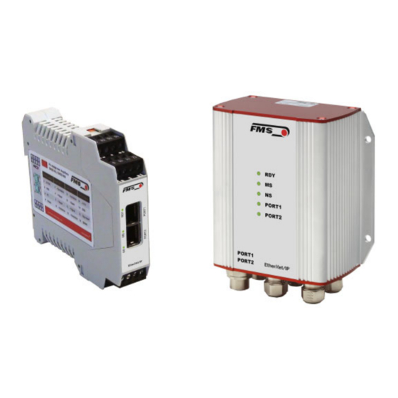
Single-channel measuring amplifier for ETHERNET/IP
EMGZ491.R.EIP for mounting on DIN rail
EMGZ491.W.EIP for wall mounting
Document Version
2.5
03/2022 NS
Firmware Version
V 2.0.4
EDS Datei
FMS_TensionAmpilfier_EMGZ491_EIP_V2_1.eds
Diese Bedienungsanleitung ist auch in Deutsch erhältlich.
Bitte kontaktieren Sie Ihre lokale FMS Vertretung.
© by FMS Force Measuring Systems AG, CH-8154 Oberglatt – All rights reserved.
Advertisement
Table of Contents

Subscribe to Our Youtube Channel
Related Manuals for FMS EMGZ491.EIP


Summary of Contents for FMS EMGZ491.EIP
- Page 1 EMGZ491.W.EIP for wall mounting Document Version 03/2022 NS Firmware Version V 2.0.4 EDS Datei FMS_TensionAmpilfier_EMGZ491_EIP_V2_1.eds Diese Bedienungsanleitung ist auch in Deutsch erhältlich. Bitte kontaktieren Sie Ihre lokale FMS Vertretung. © by FMS Force Measuring Systems AG, CH-8154 Oberglatt – All rights reserved.
-
Page 2: Table Of Contents
Operating Instruction EMGZ491.EIP 1 Table of Contents TABLE OF CONTENTS ..........................2 SAFETY INFORMATION ........................... 4 Presentation of Safety Information ..................... 4 2.1.1 Danger that Could Result in Minor or Moderate Injuries ............... 4 2.1.2 Note Regarding Proper Function ....................4 General Safety Information ........................ - Page 3 Operating Instruction EMGZ491.EIP DIMENSIONS ............................33 TECHNICAL DATA ..........................34 17.03.2022...
-
Page 4: Safety Information
Operating Instruction EMGZ491.EIP 2 Safety Information All safety information, operating and installation regulations listed here ensure proper function of the device. Safe operation of the systems requires compliance at all times. Noncompliance with the safety information or using the device outside of the specified performance data can endanger the safety and health of persons. -
Page 5: General Safety Information
Operating Instruction EMGZ491.EIP 2.2 General Safety Information The function of the measuring amplifier is only ensured with the components in the specified layout to one another. Otherwise, severe malfunctions may occur. Thus, observe the mounting information on the following pages. -
Page 6: Product Description
The measured force values are available via ETHERNET/IP and an analog voltage output. The measuring amplifiers are suitable for tension measurements using all FMS force sensors. 1 or 2 sensors can be connected to the device. Furthermore, device information, parameters, and system settings can be accessed via a web browser. -
Page 7: Quick Guide/Quick Start
Operating Instruction EMGZ491.EIP 4 Quick Guide/Quick Start In these operating instructions, commissioning of the EMGZ491.EIP amplifier is limited to the installation procedure, offset compensation, and system calibration. 4.1 Preparations for Parameterization Read the operating instructions of the selected force sensor carefully. -
Page 8: Force Sensor Mounting
The mounting instructions are included with the force sensors. 4.5 Electrical Connections One or two force sensors can be connected to the EMGZ491.EIP. When two sensors are used, they are connected in parallel internally. The force sensors and amplifier are connected using a 2x2x0.25 mm... -
Page 9: Emgz491.W.eip
Operating Instruction EMGZ491.EIP 4.5.2 EMGZ491.W.EIP The 4 screws of the cover with the PG glands and the M12 plug must be loosened for board access. You can slide out the board by approx. 2 cm (1 in.) and loosen the terminal blocks for easier connection of the wires. -
Page 10: Ethernet Connections
Operating Instruction EMGZ491.EIP 4.5.3 Ethernet Connections Table 1: pin assignment Ethernet connection EMGZ491_EIP_BA_Manual.ai Warning Poor grounding can result in electric shocks for persons, malfunctions of the overall system or damage to the measuring amplifier! Proper grounding must always be ensured. -
Page 11: Calibration Of The Measuring System
Operating Instruction EMGZ491.EIP 5 Calibration of the Measuring System There are two options for performing the calibration: Via the web browser (see 9) Directly in PLC 5.1 Offset Compensation Using offset calibration, the weight of the measuring roller and the roller bearings is compensated and the measuring system “zeroed”. -
Page 12: Calibrating
Operating Instruction EMGZ491.EIP 5.3 Calibrating Activate the web interface (see 9) and click on “Offset/Calibration” from the menu (see 9.3). Connect the first force sensor (see 4.5). The measuring signal must become positive for loads in measuring direction. If it is negative, the signal lines of the affected force sensors must be switches at the terminal block (see 4.5). -
Page 13: Limit Value Violations
Test rule: The FMS force sensors deliver 9 mV at the output under nominal force load. In the case of a load up to the mechanical stop, approx. 12.4 mV are output. These values apply, if the force sensor is loaded in normal operating direction (red point). In reverse direction, the values are respectively negative. -
Page 14: Overflow And Underflow Test
Green, on: connected Green, flashing: not connected Green, red flashing: time-out connection Red, on: dual IP Illuminates in green as soon as the EMGZ491.R EMGZ491.W voltage supply is connected and the processor is started. Figure 7: Signal LEDs on EMGZ491.EIP EMGZ491_EIP_Grafik.ai 17.03.2022... -
Page 15: Integration Into The Ethernet/Ip Network
(master) via the EDS file. The EDS file from FMS will support the EDS-AOP License Key of Rockwell. The EMGZ491.EIP transfers the actual value in digit and the status/error byte. In addition, parameters, such as offset actual value, gain actual value, filter actual value, filter analog output, as well as scaling analog output can be adjusted. -
Page 16: Configuration
Operating Instruction EMGZ491.EIP 7 Configuration The EMGZ491.EIP can be configured either via the web interface or via ETHERNET/IP. The parameters “Low-pass filter active” and “Low-pass filter analog output active” cannot be accessed via the web interface. 7.1 Modify IP address with RSLinx... - Page 17 Operating Instruction EMGZ491.EIP 17.03.2022...
-
Page 18: Parameter Description
Operating Instruction EMGZ491.EIP 7.2 Parameter Description Access daa with RSLogix 5000 Parameter Name Description Unit Here you select which unit of measurement is used. The label located on the sensor will indicate the nominal force in Newtons. Note: This input will also affect the unit of the cyclic process data. - Page 19 Operating Instruction EMGZ491.EIP Offset The values determined with the “Offset Compensation” procedure are stored in the form of a digital value in the [Offset] parameter. The value is used for compensating for the roller weight. Min. -16’000 Max. 16’000 Specified value...
- Page 20 Operating Instruction EMGZ491.EIP Limit frequency low- The amplifier features a low-pass filter that filters the pass filter actual value measured value, which is relayed via ETHERNET/IP. This filter is used for suppressing undesired interference signals that are superimposed on the measuring signal.
-
Page 21: Cyclic Data Traffic
Operating Instruction EMGZ491.EIP 7.3 Cyclic Data Traffic After a successful system start, controller and the assigned devices can exchange cyclic process data. The table below shows the measured data and how they are transmitted. Parameter Name Description Actual value in ADC Value read in via the A/D converter. - Page 22 Operating Instruction EMGZ491.EIP Actual value in unit Filtered actual value converted into configured unit. Data type long (signed 32 bit) Value range ±200‘000‘000 Value format ±#######.### for N, kN, kg, or lb The value is interpreted as decimal number with 3 decimal places.
-
Page 23: Acyclic Data Traffic
Operating Instruction EMGZ491.EIP 7.4 Acyclic Data Traffic After a successful system start, controller and the assigned devices can exchange acyclic requirement data. The following table shows the parameters and commands ad how they are transmitted using acyclic data traffic. Parameter... - Page 24 Operating Instruction EMGZ491.EIP 10244 System force The system force is the maximum permissible force of the used measuring system. Access type Parameter command system force Data type long (unsigned 32 bit) Value range 0 to 200‘000‘000 Value format ######.### Unit...
- Page 25 Operating Instruction EMGZ491.EIP 10247 Offset adjustment Determine and store offset. The system is set to zero without material tension. Access type Parameter command offset adjustment Data type byte (unsigned 8 bit) Value range 0 to 1 Value format To use the offset function a “1” must be written to the device.
- Page 26 Operating Instruction EMGZ491.EIP 10273 Analog output scaling Determines, at which force the analog output outputs the maximum value of 10 V. Access type Parameter command analog output scaling Data type long (unsigned 32 bit) Value range 100 to 200‘000‘000 Value format ######.###...
-
Page 27: Ethernet/Ip Communication
The following services and protocols are used: • Get_Attribute_Single • Set_Attribute_Single • gemäss CIP Spezifikation Volume 1 und Volume 2 All other services required for EtherNet/IP are permissible as well. The services above can be used with the EMGZ491.EIP at any time. 17.03.2022... -
Page 28: Web Interface
Operating Instruction EMGZ491.EIP 9 Web Interface 9.1 Amplifier Access via Web Interface Parameter changes or system calibration are possible via a web interface. The use of the web interface requires the knowledge of the IP address. Your IP system administrator can provide the assigned address. -
Page 29: Parameter Settings
Operating Instruction EMGZ491.EIP 9.2 Parameter Settings The Parameters page offers the option to configure the amplifier via the web interface. In the ETHERNET/IP environment, this is usually done from the PLC. Figure 11: Parameter list 17.03.2022... -
Page 30: Offset Adjustment And Calibration Via Web Browser
Operating Instruction EMGZ491.EIP 9.3 Offset Adjustment and Calibration via Web Browser The Offset/Calibration page is available for amplifier adjustment. Using this page, the offset can be adjusted and then the calibration executed. These functions are also available via PLC. If the values for offset and gain are known, they can be directly assigned to the respective parameters. -
Page 31: Ethernet Settings
Operating Instruction EMGZ491.EIP 9.4 Ethernet Settings This page shows the current TCP/IP configuration. It cannot by changed via the web interface, but read only. Changes to this configuration can only be applied via the PLC. Figure 13: Ethernet settings 17.03.2022... -
Page 32: System Settings
Operating Instruction EMGZ491.EIP 9.5 System Settings Using the System Settings page, the firmware version can be seen and new firmware can be loaded as well. Figure 14: System settings You can find the current firmware files in the download area of our website. - Page 33 Operating Instruction EMGZ491.EIP 10 Dimensions Figure 15: EMGZ491.R.EIP housing for DIN rail mounting EMGZ491_EIP_Grafik.ai Figure 16: EMGZ491.W.EIP housing for wall mounting EMGZ491_EIP_Grafik.ai 17.03.2022...
- Page 34 Operating Instruction EMGZ491.EIP 11 Technical Data Technical data Number of channels 1 channel for 2 sensors Excitation voltage 5 VDC Sensor feedback signal ± 9 mV (max. 12.5 mV) Option V05 ± 2.5 mV A/D converter resolution ± 32‘768 digit (16 bit) D/A converter resolution 0 to 4‘096 (12 bit)
- Page 35 Operating Instruction EMGZ491.EIP EtherNet/IP characteristics Cycle time ≥ 1 ms IO Connection Types Exclusive Owner; Listen Only; Input only (implicit) Number of Message Explicit message connections (10); Implizit message Connections connections (5) IO Connection Trigger Cyclic Types Baud Rate 10 or 100 Mbit/s Cyclic Process Data Actual value in Digits (ADC);...
- Page 36 Operating Instruction EMGZ491.EIP FMS Force Measuring Systems AG FMS USA, Inc. FMS (UK) FMS (Italy) Aspstrasse 6 2155 Stonington Avenue Suite 119 Aspstrasse 6 Aspstrasse 6 8154 Oberglatt (Switzerland) Hoffman Estates,, IL 60169 (USA) 8154 Oberglatt (Switzerland) 8154 Oberglatt (Switzerland) Tel.
Need help?
Do you have a question about the EMGZ491.EIP and is the answer not in the manual?
Questions and answers