Table of Contents
Advertisement
Quick Links
Operating Manual
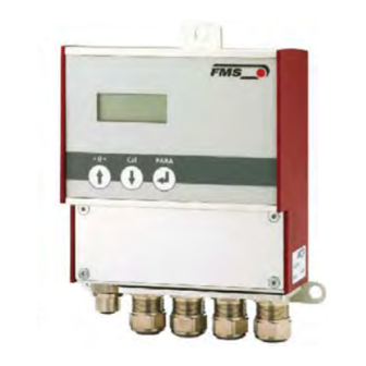
EMGZ309
Digital Microprocessor Controlled Tension Amplifier
Version 2.12
08/2017 NS
Firmware Version
V2.10
Diese Bedienungsanleitung ist auch in Deutsch erhältlich.
Bitte kontaktieren Sie Ihren nächstgelegen FMS Vertreter.
© by FMS Force Measuring Systems AG, CH-8154 Oberglatt – All rights reserved.
Advertisement
Table of Contents

Related Manuals for FMS EMGZ309


Summary of Contents for FMS EMGZ309
- Page 1 EMGZ309 Digital Microprocessor Controlled Tension Amplifier Version 2.12 08/2017 NS Firmware Version V2.10 Diese Bedienungsanleitung ist auch in Deutsch erhältlich. Bitte kontaktieren Sie Ihren nächstgelegen FMS Vertreter. © by FMS Force Measuring Systems AG, CH-8154 Oberglatt – All rights reserved.
-
Page 2: Table Of Contents
Parameter Setting via a PC ..............25 7.1 Parameterization in an Ethernet Network via Web Browser 7.2 Offset Compensation via the Web Browser 7.3 Calibration via the Web Browser 7.4 Connecting the EMGZ309 Amplifier with a PC (Peer-to-Peer) Dimensions ....................35 Technical Specification ................37 07.08.2017... -
Page 3: Safety Instructions
Operation Manual EMGZ 309 1 Safety Instructions 1.1 Description conditions a) High danger of health injury or loss of life Danger This symbol refers to high risk for persons to get health injury or loss of life. It has to be followed strictly. b) Risk of damage of machines Caution This symbol refers to informations, that, if ignored, could cause heavy mecanical... -
Page 4: System Description
2.1 Functional description The digital tension measuring amplifiers EMGZ309 are suitable for tension measurement with all FMS force sensors. This versatile product comes as a plug & play unit and is very easy to setup through the operating panel. Alternatively, more advanced users can access all the internal parameters through a Web Browser and set up the device over a PC. -
Page 5: Quick Installation Guide
Operation Manual EMGZ 309 3 Quick Installation Guide In a Plug & Play configuration the set-up of the EMGZ309 and force sensor is limited to only the offset compensation and the calibration. 3.1 Preparations for Set-up 1. Read the Operation Manual of your force measuring sensors 2. -
Page 6: Mounting The Force Sensors
However, they have to be followed strictly. 3.4 Mounting the Force Sensors Mounting of the force sensors is done according to the FMS Installation manual which is delivered together with the force sensors. 3.5 Wiring the Amplifier One or two force sensors can be connected to the measuring amplifier. - Page 7 Operation Manual EMGZ 309 Fig. 3: Wiring Diagram EMGZ309 EMGZ_309_BA_Manual.ai Ethernet connectors EMGZ_309_BA_Manual.ai Caution Bad earth ground connection may cause electric shock to persons, malfunction of the total system or damage of the electronic unit! It is vital to ensure that proper earth connection is done.
-
Page 8: Configuring The Amplifier
4 Configuring the Amplifier 4.1 Power up the EMGZ 309 1. Connect the first force sensor (see Fig.3 Wiring Diagram EMGZ309) 2. Check whether applying a force in measuring direction (in the direction of the red point) on the first sensor results in a positive output signal. If not, exchange the two signal wires of the corresponding force sensor in the terminal block (terminals 12/13). -
Page 9: Change The Measuring Units
Operating State. Or if no action is taken after 30 seconds, the value will be stored in the system automatically. 4.4 Change the Device Mode The EMGZ309 amplifiers have two Device Modes: ● Display of Force Gauge: Tension data are displayed in a force unit ●... -
Page 10: Offset Compensation Over The Operating Panel
The second method is based on a calculation method in conjunction with the FMS Calculator. This Calculator can be down loaded from the FMS web page. Please consult the factory for this option. The calibration can be performed over the Operation Panel or via the Web Browser. -
Page 11: Calibration Over The Operating Panel
Operation Manual EMGZ 309 4.8 Calibration over the Operating Panel 1. Load a rope with a defined weight corresponding to your calibration force on the roller. The roller configuration must correspond to the real configuration in the machine (wrap angle, distance of the rollers etc.). 2. -
Page 12: Analytic Calibration Method)
If necessary download and install FMS-calculator from the FMS homepage at: http://www.fms-technology.com/en/technical-information.php Gain-calculation-tool The gain calculator is an optional feature of the FMS-calculator. It delivers the gain factor for easy weightless calibration of FMS amplifiers. 1. First, the application related parameters must be entered in the FMS-calculator e.g. - Page 13 Operation Manual EMGZ 309 Fig. 8: Gain calculation tool E309_gain_e.jpg 07.08.2017...
-
Page 14: Operation
Operation Manual EMGZ309 5 Operation 5.1 Operating the EMGZ309 over the Operating Panel The EMGZ309 amplifier can go in 5 different states: • Operation State: Amplifier operating • Display Selection: Selection of force or output reading • Offset Compensation: Automatic procedure to offset the roller weight •... -
Page 15: Display Value Selection State
Operation Manual EMGZ 309 5.2 Display Value Selection State The EMGZ309 can display either a tension value or the amplifier output that is an electrical unit corresponding to the measured tension. A) For tension display following unit can be selected: N, kN, lb, g, kg B) The amplifier output can be displayed in 0…10VDC, 0…20mA or 4…20mA... -
Page 16: Parameterization Over The Operating Panel
After offset compensation and calibration the system is configured. It can now be put into operation. The following state diagrams (Fig. 10 -12) help to navigate through the parameter setting menu. In the Parameterisation State the EMGZ309 can be brought into the 2 modes: “Parameter Selection” and “Parameter Change”. - Page 17 Operation Manual EMGZ 309 The display shows the unit of measure that was previously selected. Permanent key pressing expedites the changing speed. If the Device Mode [VoltGauge] is set, these parameters are deactivated Fig. 11: State Diagram Parameter Setting (2 part) E309017e 07.08.2017...
-
Page 18: Reset To Default Parameter Set
Operation Manual EMGZ309 Fig. 12: State Diagram Parameter Setting (3 part) E309018e 6.1 Reset to Default Parameter Set Factory settings can be re-established either over the parameter setting menu (see 6.3 “Description of Parameters”) or as shown in the state diagram below: Fig. -
Page 19: Parameter List
Operation Manual EMGZ 309 6.2 Parameter List Parameter Unit Default Remarks Dis Filt. [Hz] 10.0 Out Filt. [Hz] 200.0 10.0 N, kN, lb, g, kg. Unit 100’000 1000 SysForce 100’000 1000 F@OutMax Curr.Out 0...20 or 4...20 4…20 Offset [Digit] –8000 8000 Gain 0.100... -
Page 20: Description Of Parameters
Filter Amplifier Output LCD: Out.Filt Use: The EMGZ309 contains a lowpass filter to prevent noise overlaying to the output signal. This parameter stores the cut off frequency of the filter. The lower the cut off frequency, the more sluggish the output signal will be. - Page 21 Operation Manual EMGZ 309 System Force LCD: SysForce Use: The System Force [SysForce] determines the measuring capability of your measuring roller. E.g. If two 500 N sensors are installed in your measuring roller, enter 1000N. If only one 500N sensor is used, enter 500N.
- Page 22 Use: This parameter stores the value determined with the Procedure Calibration (see 4.7 “Calibration over the Operating Panel”). Alternatively you can input a calculated value using the FMS Calculator described in chapter 4.8, if the material tension cannot be simulated.
- Page 23 Ethernet-Interface LCD: Ethernet Use: The Ethernet interface of EMGZ309 can be switched on and off with this parameter. The deactivation of this interface reduces the power consumption by 25% and lowers heat generation in the device considerably. FMS recommends to activated the Ethernet interface only when needed..
-
Page 24: Default Settings
000.000 255.255. 255.255. 000.000 255.255 255.000 LAN Speed LCD: LANSpeed Use: LANSpeed determines the data speed of the tension EMGZ309 amplifier to communicate with the receiver (Switch, Hub or PC). Parameter Range Unit Selection Default MBPS Default Settings LCD: Default Use: This menu point is a command. -
Page 25: Parameter Setting Via A Pc
Operation Manual EMGZ 309 7 Parameter Setting via a PC Fig 14 shows the EMGZ309 configuration in a LAN (Local Area Network). The EMGZ309 force measuring amplifier can be embedded in an Ethernet network and the parameter setting can be done over this network by means of a web browser (Internet Explorer 7). -
Page 26: Parameterization In An Ethernet Network Via Web Browser
In this case it must be certain that the EMGZ309 uses an IP address in a static block (not assigned by the server). For the integration of an EMGZ309 amplifier in your Ethernet network please contact your IT system administrator. - Page 27 Operation Manual EMGZ 309 Fig. 19: Current Reading for Device Mode Volt Gauge Current Reading Volt 07.08.2017...
- Page 28 Operation Manual EMGZ309 Fig. 20: Parameter list for Device Mode Force Gauge Parameters-Force Fig.21: Parameter list for Device Mode Volt Gauge Parameters-Volt 07.08.2017...
- Page 29 Operation Manual EMGZ 309 Fig. 22: Offset compensation and calibration for Device Mode Force Gauge Offset-Calibration-Force Fig. 23: Offset compensation and calibration for Device Mode Volt Gauge Offset-Calibration-Volt 07.08.2017...
-
Page 30: Offset Compensation Via The Web Browser
2. Enter the force corresponding to your calibration weight in Volt (V) in the field “Weight”. If this value is not known, the calibration method with the FMS- Calculator can be used to determine it. (see chapter 4.9 „Analytic Calibration Method“). - Page 31 Operation Manual EMGZ 309 Fig. 24: Ethernet-Settings Ethernet Settings Fig. 25: System-Settings System 07.08.2017...
-
Page 32: Connecting The Emgz309 Amplifier With A Pc (Peer-To-Peer)
The parameter setting can also be carried out with a desktop or laptop computer directly connected to the EMGZ309. In this case, the PC is connected via a Peer-to- Peer connection to the amplifier. This chapter describes the procedure for setting up a computer to communicate with EMGZ309. - Page 33 Operation Manual EMGZ 309 7. Click on Properties 8. On the next dialog box select the network adapter that is used for the connection. In our case “Internet protocol version 4 (TCP/IP)” 9. Click on Properties. The following dialog box “Internet protocol Version 4 (TCP/IPv4) Properties”...
- Page 34 The computer is now ready to communicate with the EMGZ309 amplifier: 1. Open Microsoft Internet Explorer or Mizilla Firefox. 2. The default IP address for the EMGZ309 is 192.168.000.090 as long as it was not changed over the operating penal. Enter the IP address e.g. with http://192.168.000.090...
-
Page 35: Dimensions
Operation Manual EMGZ 309 8 Dimensions The EMGZ309 series is available in three different housing options. The mechanical dimensions can be seen in the following pages. Fig. 26: Outline Drawing EMGZ309.R rail mount housing E309006e Ethernet connection: RJ-45 connector 07.08.2017... - Page 36 Operation Manual EMGZ309 Fig. 27: Outline Drawing EMGZ309.W wall mount housing E309004 Ethernet connection: M12 4-pole D-coded Fig. 28: Outline Drawing EMGZ309.S panel mount housing (RJ-45) E309005e 07.08.2017...
-
Page 37: Technical Specification
Operation Manual EMGZ 309 9 Technical Specification Sensor excitation 5VDC max. 60mA (high voltage stability) Temperature drift offset < 0.01% / K [0.006% / °F] Linearity error < 0.1% Processor cycle time Operation /Parameter Setting 3 keys and LCD 2x8 characters (size 8mm) Ethernet via web browser (Ethernet Explorer 7 Interfaces or higher) - Page 38 Operation Manual EMGZ309 07.08.2017...
- Page 39 Operation Manual EMGZ 309 07.08.2017...
- Page 40 Operation Manual EMGZ309 FMS Force Measuring Systems AG FMS Italy FMS USA, Inc. FMS UK Aspstrasse 6 Via Baranzate 67 2155 Stonington Ave. Suite 119 Highfield, Atch Lench Road 8154 Oberglatt (Switzerland) I-20026 Novate Milanese Hoffman Estates, IL 60169 USA Church Lench Tel.
Need help?
Do you have a question about the EMGZ309 and is the answer not in the manual?
Questions and answers