Table of Contents
Advertisement
Quick Links
Operating Manual
EMGZ 490
Tension Amplifier with integrated PROFINET Interface
Version 1.3
09/2015 NS
Firmware Version
V1.16
GSDML file
V2.3
This operation manual is also available in German.
Please contact your local FMS representative.
Diese Bedienungsanleitung ist auch in Deutsch erhältlich.
Bitte kontaktieren Sie Ihren nächstgelegenen FMS Vertreter.
© by FMS Force Measuring Systems AG, CH-8154 Oberglatt – All rights reserved
Advertisement
Table of Contents

Subscribe to Our Youtube Channel
Related Manuals for FMS EMGZ 490


Summary of Contents for FMS EMGZ 490
- Page 1 This operation manual is also available in German. Please contact your local FMS representative. Diese Bedienungsanleitung ist auch in Deutsch erhältlich. Bitte kontaktieren Sie Ihren nächstgelegenen FMS Vertreter. © by FMS Force Measuring Systems AG, CH-8154 Oberglatt – All rights reserved...
-
Page 2: Table Of Contents
Description Conditions ..................... 4 List of safety instructions ....................4 Product Description ................6 Product Range ........................6 Block Diagram EMGZ 490 ....................6 System Description EMGZ 490 ..................6 Quick Installation Guide ..............7 Preparations for Set-up ....................7 Installation Procedure ...................... - Page 3 Operation Manual EMGZ 490 Parameter Setting ......................28 Offset Compensation and Calibration over the Web Browser ........ 29 Ethernet Settings ......................30 System Settings ......................31 Mechanical Dimensions ..............32 Technical Specification ..............34 10.1 PROFINET Characteristics ..................... 34 10.2 Technical Features ......................
-
Page 4: Safety Instructions
Operation Manual EMGZ 490 1 Safety Instructions All safety related regulations, local codes and instructions that appear in the manual or on equipment must be observed to ensure personal safety and to prevent damage to the equipment connected to it. If equipment is used in a manner not specified by the manufacturer, the protection provided by the equipment may be impaired. - Page 5 Operation Manual EMGZ 490 Bad earth connection may cause electric shock to persons, malfunction of the total system or damage of the electronic unit! It is vital to ensure that proper earth connection is done. Improper handling of the electronic boards may cause damage to the fragile equipment! Don’t use rough tools such as screwdrivers or pliers! Operators handling...
-
Page 6: Product Description
Operation Manual EMGZ 490 2 Product Description 2.1 Product Range The tension amplifier EMGZ 490 series is available in three different housing options. ● EMGZ 490.R DIN-rail mount housing ● EMGZ 490.Ro DIN-rail mount open version ● EMGZ 490.W Wall mount housing For detailed information about the mechanical dimensions refer to the outline drawings in chapter 9. -
Page 7: Quick Installation Guide
Operation Manual EMGZ 490 3 Quick Installation Guide The set-up of the EMGZ 490 and force sensors is limited to only the installation procedure, offset compensation and the calibration. 3.1 Preparations for Set-up 1. Read the Operation Manual of your force measuring sensors 2. -
Page 8: Wiring The Amplifier
The cable must be installed separate from power lines. Fig. 2: Wiring Diagram EMGZ 490 Color scheme (IEC60757) and pin codes are valid for FMS components, only! Caution Bad earth connection may cause electric shock to persons, malfunction of the total system or damage of the electronic unit! It is vital to ensure that proper earth connection is done. -
Page 9: Calibration Of The Measuring System
Calculator. This Calculator can be down loaded from the FMS web page. FMS recommends using the method with the weight (see Fig. 3) since it delivers the most accurate results. To set the Gain, load a rope with a defined weight on the roller. -
Page 10: Calibration Procedure
Operation Manual EMGZ 490 4.3 Calibration Procedure 1. Activate web interface (ref. to chapter 8.1) and call web page „Offset/Calibration over the web browser” (see chapter 8.3). 2. Connect volt meter to the voltage output (Fig. 2, terminal 4/5) 3. Connect first force sensor to the amplifier (see Fig. 2). -
Page 11: Limit Violations
It replaces the binary value (first digit). This calculation method is also used by the FMS Calculator tool. Thus it is possible to use the gain value calculated by the FMS Calculator directly in the calibration. The gain value is then In this entered in the parameter set of the amplifier (see chapter 8.2 “Parameter Setting”). -
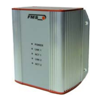
Page 12: Description Of Signal-Leds
Blinking, if data communication on ACT 1 Ethernet connection 1 active Ethernet cable 2 connected with LNK 2 other station Blinking, if data communication on ACT 2 Ethernet connection 2 active Fig. 4: Signal LEDs on EMGZ 490.R and EMGZ 490.W 15.12.2015... -
Page 13: Integration In A Profinet-Network
The MAC-address is part of the network card of the corresponding device. It is set at the factory for each EMGZ 490 device and subsequently it cannot be changed. The MAC-address is lost after a firmware update. -
Page 14: Tcp/Ip Configuration
The IP-address is assigned to each device via the PLC. The device must have an IP-address of 0.0.0.0 after power up to enable the assignment of the final IP-address. This is the case after each EMGZ 490 restart. Static IP-address: A static IP-address is required to enable the PLC accessing a web interface. -
Page 15: System Start-Up
Operation Manual EMGZ 490 The EMGZ 490 uses the static IP address 192.168.0.90, if the digital input 1 is activated. To activate Dig. In 1 connect terminal 1 with 6 (24VDC with Dig. In 1) (see Fig. 2). In this case the IP- address cannot be changed. Since every device has an unique address in the same network, a re-assignment via an PLC is not possible. -
Page 16: Configuration
Operation Manual EMGZ 490 6 Configuration The configuration of the EMGZ 490 can be performed either over a web interface or over PROFINET. In both case the same parameters are configured. 6.1 Description of Parameters PROFINET Filter Use: The amplifier provides a low-pass filter for PROFINET data to prevent noise and interferences being overlaid to the PROFINET output. - Page 17 Operation Manual EMGZ 490 Tension at Max. Output Use: This parameter defines what force value (N, kN, lb, g, kg) corresponds to the maximum output of the amplifier (10V). Note: By changing the units to lb the whole unit system will change from metric to imperial units.
-
Page 18: Cyclic Data Traffic
Operation Manual EMGZ 490 6.2 Cyclic Data Traffic After a successful system boot the IO-controller and associated IO-devices can start exchanging cyclic process data. The following table shows which data are transmitted and in which form. Cyclic Data User Data... -
Page 19: Acyclic Data Traffic
Operation Manual EMGZ 490 6.3 Acyclic Data Traffic After a successful system boot the IO-controller and associated IO-devices can start exchanging acyclic data. The table below shows which parameters and instructions are transmitted. Acyclic Data Parameter Data Range Description Instruction... - Page 20 Operation Manual EMGZ 490 Parameter Data Range Description Instruction Type Scaling unsigned #0.000 N Determines at Analogue long what force the Output (unsigne analogue output 200‘000‘000 d 32 Bit) outputs the its maximal value 10V. Cut-off unsigned #0.0 Cut-off frequency...
-
Page 21: Profinet Communication
The Read-/Write-instructions can be triggered if a connection between controller and IO- device was established; say a "Connect" was done. Fig. 5: Read- / Write-cycle EMGZ 490 E490011 The computer with the corresponding application can now request a read or write cycle to the data model of the controller. -
Page 22: Limitations
Operation Manual EMGZ 490 7.3 Limitations In order for the EMGZ490 to not reach system limitations, one should avoid the use of some services during operation. These services are: • Port scanning • Web services • Stress tests • As well as all other not-PROFINET related services and protocols •... -
Page 23: Data Blocks
Operation Manual EMGZ 490 The individual FBs read or write their data to data blocks, which are listed below Fig. 6: Functional Blocks FB1 – FB2 E490012 7.5 Data Blocks In a controller, data blocks can be configured. As FBs they can be easier apply and monitored by the computer. -
Page 24: Trigger Read-/Write-Instructions
Operation Manual EMGZ 490 The following graph (Fig. 7) shows the connection between FBs and DBs, respectively how the access from FB to individual DBs is done. Fig. 7: Connection between functional blocks and data blocks E490013 7.6 Trigger Read-/Write-instructions Proceed as follows to initiates a Read-/Write-instruction by the controller: ●... -
Page 25: Configuration File Gsdml
Operation Manual EMGZ 490 7.7 Configuration File GSDML Thus, the acyclic data traffic can operate independently from the cyclic, and the two don’t interfere with each other, a new module in the PROFINET IO-device configuration was introduced. The graph (Fig. 8) shows the actual module configuration: Fig. -
Page 26: Web Interface
Using the web interface requires knowledge of the IP address. Your IT system administrator can provide information about the assigned addresses. After entering the IP address in your web browser the home page of EMGZ 490 will appear (see Fig. 10). Caution The web interface may only be used in the test mode since data communication can interfere with the PLC. - Page 27 Operation Manual EMGZ 490 Fig. 11: Current Reading E490016 The web page Current Reading shows the actual values of the amplifier. The first line “Tension” shows the tension at the input in the configured unit of measure. In the second line “Output” indicates the output voltage shown in Volt.
-
Page 28: Parameter Setting
Operation Manual EMGZ 490 8.2 Parameter Setting Fig. 12: Parameter list E490017 The web page Parameters provides the possibility to configure the amplifier via the web interface. It is to notice that in a PROFINET-environment this is usually done via the PLC... -
Page 29: Offset Compensation And Calibration Over The Web Browser
Operation Manual EMGZ 490 8.3 Offset Compensation and Calibration over the Web Browser .For gain adjustment the page Offset / Calibration is available. This page offset compensation and calibration. These functions are also available via the PLC. If the offset and gain values known, they can be entered directly to these parameters. -
Page 30: Ethernet Settings
Operation Manual EMGZ 490 8.4 Ethernet Settings This page displays the actual TCP / IP-configuration. It cannot be changed via the web interface. Changes to this configuration have to be done over the PLC. Fig.14: Ethernet Settings E490019 15.12.2015... -
Page 31: System Settings
Operation Manual EMGZ 490 8.5 System Settings Via the page System Settings, the internal firmware version is displayed. Furthermore, a new firmware can be up-loaded. Fig. 15: System Settings E490020 15.12.2015... -
Page 32: Mechanical Dimensions
Operation Manual EMGZ 490 9 Mechanical Dimensions The EMGZ 490 series is available in two different housing options. Fig. 16: Outline Drawing EMGZ309.R rail mount housing E490002e Ethernet connection: RJ-45 connector 107.3 [4.2“] 65 [2.56“] Fig. 16: Outline Drawing EMGZ309.Ro rail mount housing open version... - Page 33 Operation Manual EMGZ 490 Fig. 17: Outline Drawing EMGZ309.W wall mount housing E490003e Ethernet connection: M12 4-pole D-coded 15.12.2015...
-
Page 34: Technical Specification
Device ID via MAC- Setting device-ID over MAC-address resp. configuration of address MAC-address via external IO-Pin Remote Flash Update Specially developed Flash-update for up-loading new FPGA/SW-loads Web service Measuring data can be requested via http, EMGZ 490 can be configured and adjusted. 15.12.2015... -
Page 35: Hardware Specification
<0.05% FS Cycle for Data Exchange ≥ 1ms Interface Connectors EMGZ 490.R: 2x RJ-45 EMGZ 490.W: 2x M12 4-pole D-coded Parameter Setting over PROFINET or web interface Certification PROFINET specification V2.1, CC-B POFINET IO net load guide line Version 1.0, Nov. 2010; Order No. 7.302 Power Supply 24VDC (18...36VDC) / 5W... - Page 36 Operation Manual EMGZ 490 MS Force Measuring Systems AG FMS Italy FMS USA, Inc. FMS UK Aspstrasse 6 Via Baranzate 67 2155 Stonington Ave. Suite 119 Highfield, Atch Lench Road 8154 Oberglatt (Switzerland) I-20026 Novate Milanese Hoffman Estates, IL 60169 USA Church Lench Tel.
Need help?
Do you have a question about the EMGZ 490 and is the answer not in the manual?
Questions and answers