Table of Contents
Advertisement
Quick Links
Operating Manual
EMGZ306A/ EMGZ306A.10V
EMGZ306A.CAL
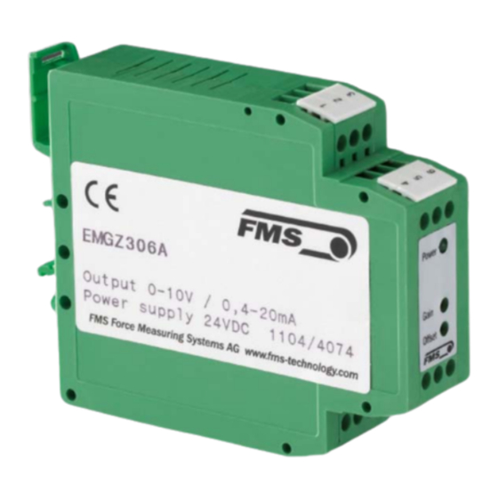
Compact analogue Tension Measuring Amplifier
Document Version
2.2 08/2017 NS
Diese Bedienungsanleitung ist auch in Deutsch, Französisch und Italienisch erhältlich.
Bitte kontaktieren Sie Ihren nächstgelegenen FMS Vertreter.
© by FMS Force Measuring Systems AG, CH-8154 Oberglatt – All rights reserved.
Advertisement
Table of Contents

Subscribe to Our Youtube Channel
Summary of Contents for FMS EMGZ306A
- Page 1 Compact analogue Tension Measuring Amplifier Document Version 2.2 08/2017 NS Diese Bedienungsanleitung ist auch in Deutsch, Französisch und Italienisch erhältlich. Bitte kontaktieren Sie Ihren nächstgelegenen FMS Vertreter. © by FMS Force Measuring Systems AG, CH-8154 Oberglatt – All rights reserved.
-
Page 2: Table Of Contents
View of the Setting Elements EMGZ306A View of the Setting Elements EMGZ306A.CAL Configuring the Outputs Configuring the Lowpass Filter Calibrating the Measuring Amplifier Calibrating the Measuring Amplifier without a Weight (EMGZ306A.CAL only)12 Trouble Shooting ..................15 Technical Data ..................15... -
Page 3: Safety Instructions
Operating manual EMGZ306A 1 Safety Instructions 1.1 Description conditions a) High danger of health injury or loss of life Danger This symbol refers to high risk for persons to get health injury or loss life. It has to be followed strictly. -
Page 4: Definitions
Strain gauge: The electronic component that will change its resistance while its length has changed. Strain gauges are used in the FMS force sensors for acquisition of the feedback value. 3 System Components The EMGZ306A consists of the following components (refer also to Fig. 1): Force sensors •... -
Page 5: System Description
Due to the wheatstone wiring of the strain gauges, the measured value is according also to the power supply. So, the force sensors are supplied from the EMGZ306A by a very accurate power supply. -
Page 6: Block Diagram
Operating manual EMGZ306A 4.5 Block Diagram Fig. 2 E306007e 4.6 Dimensions Fig. 3 E306008us... -
Page 7: Installation And Wiring
(Fig. 4). 5.2 Mounting the force sensors Mounting of the force sensors is done referring to the FMS Installation manual which is delivered together with the force sensors. Wiring to the terminals of the electronic unit is done according to wiring diagram (Fig. -
Page 8: Wiring
Operating manual EMGZ306A 5.3 Wiring Fig. 4: Wiring Diagram E306009e There can be connected 1 or 2 force sensors to the measuring amplifier. Using 2 force sensors, the connections will be wired parallel. The output signal of the measuring amplifier then will correspond to the average value of the 2 sensors. -
Page 9: Setting Into Operation
Operating manual EMGZ306A 6 Setting into Operation 6.1 View of the Setting Elements EMGZ306A . 5a: Setting elements EMGZ306A. The LED is for monitoring the supply voltage E306010e 6.2 View of the Setting Elements EMGZ306A.CAL terminals Power CAL button Gain... -
Page 10: Configuring The Outputs
(0...20mA or 4...20mA) which are active simultaneously. The signal of the current output is configured as follows: Current output 4...20mA The jumpers have to be set to X1 / X2 (fig. 6). This is the standard FMS factory setting. Fig. 6: Jumper setting for current output 4...20mA E306006a Current output 0...20mA... -
Page 11: Calibrating The Measuring Amplifier
Operating manual EMGZ306A Cut-off frequency [Hz] Capacitor [μF] C = 10 / F C: Capacity [μF] F: Cut-off frequency [Hz] 0.05 0.02 1000 0.01 Note You must not use electrolytic capacitors because positive and negative signals are appearing! They would damage the electrolytic capacitor. -
Page 12: Calibrating The Measuring Amplifier Without A Weight (Emgz306A.cal Only)12
6.6 Calibrating the Measuring Amplifier without a Weight (EMGZ306A.CAL only) The EMGZ306A.CAL has a calibration button on the front side. Pushing this button simulates an input of 4.5mV at the amplifiers. This is used as reference point for the calibration without weight. - Page 13 The Gain Calculator is a tool for easy weightless calibration of FMS digital amplifiers and FMS analogue amplifier EMGZ306A.CAL. 1. First go through step 1 to 4 in the FMS-calculator and fill-in all relevant data. 2. Choose the appropriate sensor type.
- Page 14 6. Insert material or a rope loosely to the machine. 7. Adjust the offset trimmer until the output value is zero. 8. Connect a voltmeter to the voltage output of the EMGZ306A.CAL, press the CAL button and simultaneously adjust the gain potentiometer until the output reads the “Output Voltage”...
-
Page 15: Trouble Shooting
Operating manual EMGZ306A 7 Trouble Shooting Error Cause Corrective action Output shows signal > 0 Offset setting is bad Re-adjust offset (refer to „7.4 Calibrating the measuring although material has no tension amplifier“) Current output is Change jumper setting if... - Page 16 Operating manual EMGZ306A FMS Force Measuring Systems AG FMS Italy FMS USA, Inc. FMS UK Aspstrasse 6 Via Baranzate 67 2155 Stonington Ave. Suite 119 Highfield, Atch Lench Road 8154 Oberglatt (Switzerland) I-20026 Novate Milanese Hoffman Estates, IL 60169 USA Church Lench Tel.


Need help?
Do you have a question about the EMGZ306A and is the answer not in the manual?
Questions and answers