Table of Contents
Advertisement
Quick Links
Operating Instructions
EMGZ492.PNET
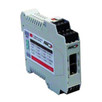
Dual-channel measuring amplifier for PROFINET IO
EMGZ492.R.PNET for mounting on DIN rail
EMGZ492.W.PNET for wall mounting
Dokument Version
1.2, 10/2018 NS
Firmware Version
V 1.1.1
GSDML Datei
GSDML-V2.32-FMS-EMGZ491_492-20161130.xml
Diese Bedienungsanleitung ist auch in Deutsch erhältlich.
Bitte kontaktieren Sie Ihre lokale FMS Vertretung.
© by FMS Force Measuring Systems AG, CH-8154 Oberglatt – Alle Rechte vorbehalten.
Advertisement
Table of Contents

Related Manuals for FMS EMGZ492.PNET


Summary of Contents for FMS EMGZ492.PNET
- Page 1 EMGZ492.W.PNET for wall mounting Dokument Version 1.2, 10/2018 NS Firmware Version V 1.1.1 GSDML Datei GSDML-V2.32-FMS-EMGZ491_492-20161130.xml Diese Bedienungsanleitung ist auch in Deutsch erhältlich. Bitte kontaktieren Sie Ihre lokale FMS Vertretung. © by FMS Force Measuring Systems AG, CH-8154 Oberglatt – Alle Rechte vorbehalten.
-
Page 2: Table Of Contents
Operating Instructions EMGZ492.PNET 1 Table of Contents TABLE OF CONTENTS ..........................2 SAFETY INFORMATION ........................... 4 Presentation of Safety Information ..................... 4 2.1.1 Danger that Could Result in Minor or Moderate Injuries ............... 4 2.1.2 Note Regarding Proper Function ....................4 General Safety Information ........................ - Page 3 Operating Instructions EMGZ492.PNET DIMENSIONS ............................37 TECHNICAL DATA ..........................38 05.10.2018...
-
Page 4: Safety Information
Operating Instructions EMGZ492.PNET 2 Safety Information All safety information, operating and installation regulations listed here ensure proper function of the device. Safe operation of the systems requires compliance at all times. Noncompliance with the safety information or using the device outside of the specified performance data can endanger the safety and health of persons. -
Page 5: General Safety Information
Operating Instructions EMGZ492.PNET 2.2 General Safety Information The function of the measuring amplifier is only ensured with the components in the specified layout to one another. Otherwise, severe malfunctions may occur. Thus, observe the mounting information on the following pages. -
Page 6: Product Description
The measured force values are available via PROFINET and an analog voltage output. The measuring amplifiers are suitable for tension measurements using all FMS load cells. Two force sensors A and B can be connected to the device. Both measuring values are available as individual signal (A and B), as sum signal (A + B), as differential signal |A –... -
Page 7: Quick Guide/Quick Start
Operating Instructions EMGZ492.PNET 4 Quick Guide/Quick Start In these operating instructions, commissioning of the EMGZ492.PNET amplifier is limited to the installation procedure, offset compensation, and system calibration. 4.1 Preparations for Parameterization Read the operating instructions of the selected load cell carefully. -
Page 8: Load Cell Mounting
The mounting instructions are included with the load cells. 4.5 Electrical Connections Two or four load cells can be connected to the EMGZ492.PNET. When four sensors are used, two of them have to be connected in parallel. The load cells and amplifier are connected using a 2x2x0.25 mm... -
Page 9: Emgz492.W.pnet
Operating Instructions EMGZ492.PNET Figure 3: Detachable terminal blocks: use a small slotted screwdriver as a lever 4.5.2 EMGZ492.W.PNET The 4 screws of the cover with the PG glands and the M12 plug must be loosened for board access. You can slide out the board by approx. 2 cm (1 in.) and loosen the terminal blocks for easier connection of the wires. -
Page 10: Ethernet Anschlüsse
Operating Instructions EMGZ492.PNET 4.5.3 Ethernet Anschlüsse Tabelle 1: Pin Belegung Ethernet Anschluss EMGZ492_PNET_Grafik.ai Warning Poor grounding can result in electric shocks for persons, malfunctions of the overall system or damage to the measuring amplifier! Proper grounding must always be ensured. -
Page 11: Calibration Of The Measuring System
If the material tension in the machine cannot be replicated using the weight method (e.g., for space reasons), the gain can be calculated using the “FMS-Calculator”. This tool can be downloaded from the FMS homepage. Figure 6: Replication of the material profile using a defined weight Tension_Control_Solutions.ai... -
Page 12: Calibration
Operating Instructions EMGZ492.PNET 5.3 Calibration Activate the web interface (see 9) and click on “Offset/Calibration” from the menu (see 9.3). Connect the first load cell (see 4.5). The measuring signal must become positive for loads in measuring direction. If it is negative, the signal lines of the affected load cells must be switches at the terminal block (see 4.5). -
Page 13: Limit Value Violations
Test rule: The FMS load cells deliver 9 mV at the output under nominal force load. In the case of a load up to the mechanical stop, approx. 12.4 mV are output. These values apply, if the load cell is loaded in normal operating direction (red point). In reverse direction, the values are respectively negative. -
Page 14: Overflow And Underflow Test
Illuminates in red if no RJ45 plug is connected. Flashes red if communication with the PLC is interrupted. Not used .R-Version .W-Version Illuminates in green as soon as the voltage supply is connected and the processor is started. Figure 7: Signal LEDs on EMGZ492.PNET EMGZ491_PNET_Grafik.ai 05.10.2018... -
Page 15: Integration Into The Profinet Network
6.1 PROFINET Interface PROFINET RT is supported. The respective communication profile is selected by the IO controller (master) via the GSD. The EMGZ492.PNET transfers the actual value in digit and the status/error byte. In addition, parameters, such as offset actual value, gain actual value, filter actual value, filter analog output, as well as scaling analog output can be adjusted. -
Page 16: Configuration
Operating Instructions EMGZ492.PNET 7 Configuration The EMGZ492.PNET can be configured either via the web interface or via PROFINET. The parameters “Low-pass filter active” and “Low-pass filter analog output active” cannot be accessed via the web interface. 7.1 Parameter Description Parameter... - Page 17 Operating Instructions EMGZ492.PNET Nominal force A The nominal force indicates the measuring capacity of force sensor A. E.g., if a 500 N load cells is installed 500 N must be entered. Unit Min. 1.00 Max. 200‘000.00 Specified value 1‘000.00 Limit frequency low-...
- Page 18 Operating Instructions EMGZ492.PNET Nominal force B The nominal force indicates the measuring capacity of force sensor B. E.g., if a 500 N load cells is installed 500 N must be entered. Unit Min. 1.00 Max. 200‘000.00 Specified value 1‘000.00 Limit frequency low-...
-
Page 19: Cyclic Data Traffic
Operating Instructions EMGZ492.PNET Analog output scaling This parameter determines, for which force the analog output outputs its maximum voltage (10 V). Note: If lb (pound) is selected, the system switches from metric to imperial measuring units. Unit Min. Max. 200‘000.00 Specified value 1‘000.00... - Page 20 Operating Instructions EMGZ492.PNET Actual value A in unit Filtered actual value converted into configured unit. Data type long (signed 32 bit) Value range ±200‘000‘000 Value format ±#######.### for N, kN, kg, or lb The value is interpreted as decimal number with 3 decimal places.
- Page 21 Operating Instructions EMGZ492.PNET Actual value B in unit Filtered actual value converted into configured unit. Data type long (signed 32 bit) Value range ±200‘000‘000 Value format ±#######.### for N, kN, kg, or lb The value is interpreted as decimal number with 3 decimal places.
-
Page 22: Acyclic Data Traffic
Operating Instructions EMGZ492.PNET Actual value (A + B)/2 Filtered actual values medium signal converted into in unit configured unit. Data type long (signed 32 bit) Value range ±200‘000‘000 Value format ±#######.### for N, kN, kg, or lb The value is interpreted as decimal number with 3 decimal places. - Page 23 Operating Instructions EMGZ492.PNET Figure 8: parameter access point for acyclic data traffic Parameter Index Description 0x01 Unit Access type Parameter command unit Data type byte (unsigned 8 bit) Value range 0 to 4 0=N; 1=kN; 2=lb; 3=g; 4=kg Value format...
- Page 24 Operating Instructions EMGZ492.PNET 0x02 Offset A Access type Parameter command offset Data type int (unsigned 16 bit) Value range -16‘000 to 16‘000 Value format ±##### 0x03 Gain A Access type Parameter command gain Data type int (unsigned 16 bit) Value range 100 to 20‘000...
- Page 25 Operating Instructions EMGZ492.PNET 0x06 Limit frequency low-pass filter actual value A Limit frequency of the low-pass filter for the actual value outputted via PROFINET. Access type Parameter command limit frequency low-pass filter actual value (PROFINET) Data type int (unsigned 16 bit) Value range 1 to 2‘000...
- Page 26 Operating Instructions EMGZ492.PNET 0x0A Gain B Access type Parameter command gain Data type int (unsigned 16 bit) Value range 100 to 20‘000 Value format ##.### 0x0B Nominal force B The nominal force is the maximum permissible force of the used measuring system.
- Page 27 Operating Instructions EMGZ492.PNET 0x0D Limit frequency low-pass filter actual value B Limit frequency of the low-pass filter for the actual value outputted via PROFINET. Access type Parameter command limit frequency low-pass filter actual value (PROFINET) Data type int (unsigned 16 bit) Value range 1 to 2‘000...
- Page 28 Operating Instructions EMGZ492.PNET 0x20 Output value 0 = (A +B)/2 1 = A + B 2 = |A - B| 3 = A 4 = B 05.10.2018...
- Page 29 Operating Instructions EMGZ492.PNET 0x21 Analog output scaling Determines, at which force the analog output outputs the maximum value of 10 V. Access type Parameter command analog output scaling Data type long (unsigned 32 bit) Value range 100 to 200‘000‘000 Value format ######.###...
-
Page 30: Profinet Communication
All other services required for PROFINET are permissible as well. The services above can be used with the EMGZ492.PNET at any time. Further services can be used, if they do not exceed the net load in line with Net Load Class III for normal operation. -
Page 31: Web Interface
Operating Instructions EMGZ492.PNET 9 Web Interface 9.1 Amplifier Access via Web Interface Parameter changes or system calibration are possible via a web interface. The use of the web interface requires the knowledge of the IP address. Your IP system administrator can provide the assigned address. - Page 32 Operating Instructions EMGZ492.PNET Figure Current Reading (current measured values) The Current Reading page displays all current values of the amplifier. The first line Tension shows the tensile force measured at the input in the adjusted unit. In the second line Output, the output voltage is displayed in Volts.
-
Page 33: Parameter Settings
Operating Instructions EMGZ492.PNET 9.2 Parameter Settings The Parameters page offers the option to configure the amplifier via the web interface. In the PROFINET environment, this is usually done from the PLC. Figure 11: Parameter list 05.10.2018... -
Page 34: Offset Adjustment And Calibration Via Web Browser
Operating Instructions EMGZ492.PNET 9.3 Offset Adjustment and Calibration via Web Browser The Offset/Calibration page is available for amplifier adjustment. Using this page, the offset can be adjusted and then the calibration executed. These functions are also available via PLC. If the values for offset and gain are known, they can be directly assigned to the respective parameters. -
Page 35: Ethernet Settings
Operating Instructions EMGZ492.PNET 9.4 Ethernet Settings This page shows the current TCP/IP configuration. It cannot by changed via the web interface, but read only. Changes to this configuration can only be applied via the PLC. Figure 13: Ethernet settings 05.10.2018... -
Page 36: System Settings
Operating Instructions EMGZ492.PNET 9.5 System Settings Using the System Settings page, the firmware version can be seen and new firmware can be loaded as well. Figure 14: System settings You can find the current firmware files in the download area of our website. - Page 37 Operating Instructions EMGZ492.PNET 10 Dimensions Figure 15: EMGZ492.R.PNET housing for DIN rail mounting Figure 16: EMGZ492.W.PNET housing for wall mounting 05.10.2018...
- Page 38 Operating Instructions EMGZ492.PNET 11 Technical Data Technische Daten Number of channels 2 channels for 2 or 4 force sensors Load cell power supply 5 VDC, max. 80 mA, highly stable Input signal range ± 9 mV (max. 12.5 mV) A/D converter ±...
- Page 39 Remote Flash Update Flash update routine for uploading SW updates Web service Configuration, measured data can be inquired via http. (EMGZ492.PNET can also be configured via PROFINET) Multiple Application 1 OP AR; 1 Supervisory AR Relation PROFINET IO V 2.3, legacy startup of specification V 2.2 is supported...
- Page 40 Operating Instructions EMGZ492.PNET FMS Force Measuring Systems AG FMS USA, Inc. FMS (UK) FMS Italy Aspstrasse 6 2155 Stonington Avenue Suite 119 Highfield, Atch Lench Road Via Baranzate 67 8154 Oberglatt (Switzerland) Hoffman Estates,, IL 60169 (USA) Church Lench 20026 Novate Milanese Tel.
Need help?
Do you have a question about the EMGZ492.PNET and is the answer not in the manual?
Questions and answers