METREL EurotestCOMBO MI 3125 Instruction Manual
Hide thumbs
Also See for EurotestCOMBO MI 3125:
- Short instructions (24 pages) ,
- Instruction manual (60 pages) ,
- Instruction manual (88 pages)

Related Manuals for METREL EurotestCOMBO MI 3125


Summary of Contents for METREL EurotestCOMBO MI 3125
-
Page 1: Instruction Manual
EurotestCOMBO MI 3125 / MI 3125E Instruction manual Version 2.3.2, Code no 20 751 483 Source document version: 2.2.1, Code no 20 751 483... - Page 2 (European Union) concerning safety and electromagnetic compatibility regulations © 2017 METREL The trade names Metrel, Smartec, Eurotest, Autosequence are trademarks registered or pending in Europe and other countries. No part of this publication may be reproduced or utilized in any form or by any means...
-
Page 3: Table Of Contents
MI 3125 / MI 3125E EurotestCOMBO Table of contents Table of contents Preface ........................5 Safety and operational considerations ..............6 Warnings and notes ..................6 Battery and charging ..................9 2.2.1 New battery cells or cells unused for a longer period ..........10 Standards applied ................... - Page 4 MI 3125 / MI 3125E EurotestCOMBO Table of contents Fuse replacement .................... 50 Cleaning ......................50 Periodic calibration ..................50 Upgrading the instrument ................50 Service ......................51 Technical specifications ..................52 Insulation resistance ..................52 Continuity & Ring (r ) .............
-
Page 5: Preface
In order for operator to be familiar enough with performing measurements in general and their typical applications it is advisable to read Metrel handbook Guide for testing and verification of low voltage installations. The instrument is equipped with the entire necessary accessory for comfortable testing. -
Page 6: Safety And Operational Considerations
2.1 Warnings and notes In order to maintain the highest level of operator safety while carrying out various tests and measurements Metrel recommends keeping your Eurotest instruments in good condition and undamaged. When using the instrument, consider the following general warnings: symbol on the instrument means »Read the Instruction manual... - Page 7 MI 3125 / MI 3125E EurotestCOMBO Safety and operational considerations Warnings related to measurement functions: Insulation resistance Insulation resistance measurement should only be performed on de-energized objects! Do not touch the test object during the measurement or before it is fully ...
- Page 8 MI 3125 / MI 3125E EurotestCOMBO Safety and operational considerations Continuity functions If voltages of higher than 10 V (AC or DC) is detected between test terminals, the continuity resistance test will not be performed. Before performing a continuity measurement, where necessary, compensate test ...
-
Page 9: Battery And Charging
If the instrument is not to be used for a long period of time, remove all batteries from the battery compartment. Alkaline or rechargeable Ni-Cd or Ni-MH batteries (size AA) can be used. Metrel recommends only using rechargeable batteries with a capacity of 2100mAh or above. -
Page 10: New Battery Cells Or Cells Unused For A Longer Period
Ni-Cd cells can be subjected to these chemical effects (sometimes called the memory effect). As a result the instrument operation time can be significantly reduced during the initial charging/discharging cycles of the batteries. In this situation, Metrel recommend the following procedure to improve the battery lifetime: Procedure Notes Completely charge the battery. - Page 11 MI 3125 / MI 3125E EurotestCOMBO Safety and operational considerations Safety (LVD) BS EN 61010-1 Safety requirements for electrical equipment for measurement, control and laboratory use – Part 1: General requirements BS EN 61010- Safety requirements for hand-held probe assemblies for electrical measurement and test BS EN 61010-2- Safety requirements for electrical equipment for measurement,...
-
Page 12: Instrument Description
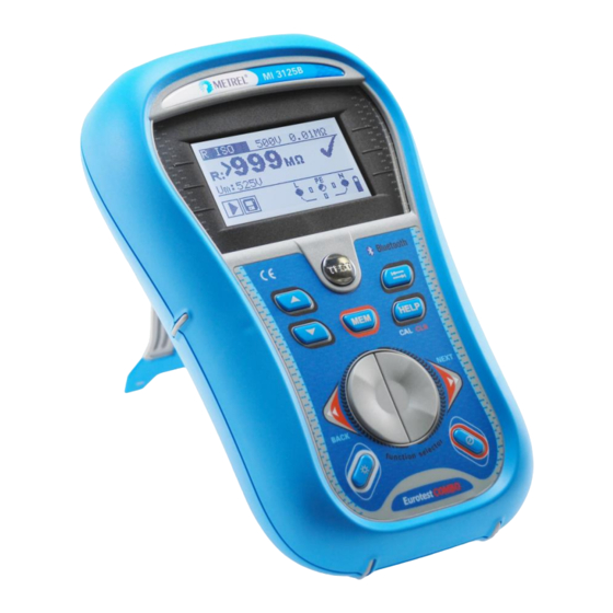
MI 3125 / MI 3125E EurotestCOMBO Instrument description 3 Instrument description 3.1 Front panel Figure 3.1: Front panel Legend: 1 LCD 128 x 64 dots matrix display with backlight. 2 TEST Starts measurements. TEST Acts also as the PE touching electrode. 3 UP Modifies selected parameter. -
Page 13: Connector Panel
MI 3125 / MI 3125E EurotestCOMBO Instrument description 3.2 Connector panel Figure 3.2: Connector panel Legend: 1 Test connector Measuring inputs / outputs 2 Protection cover 3 Charger socket 4 PS/2 connector Serial port for upgrading the instrument. Warnings! Maximum allowed voltage between any test terminal and ground is 600 V! ... -
Page 14: Back Side
MI 3125 / MI 3125E EurotestCOMBO Instrument description 3.3 Back side Figure 3.3: Back side Legend: Side belt Battery compartment cover Fixing screw for battery compartment cover Back panel information label Holder for inclined position of the instrument Magnet for fixing instrument close to tested item (optional) Figure 3.4: Battery compartment Legend: Battery cells... -
Page 15: Display Organization
MI 3125 / MI 3125E EurotestCOMBO Instrument description 3.4 Display organization Function name Result field Test parameter field Message field Terminal voltage monitor Figure 3.5: Typical function display Battery indication 3.4.1 Terminal voltage monitor The terminal voltage monitor displays on-line the voltages on the test terminals and information about active test terminals. -
Page 16: Result Field
MI 3125 / MI 3125E EurotestCOMBO Instrument description RCD tripped-out during the measurement (in RCD functions). Instrument is overheated. The measurement is prohibited until the temperature decreases under the allowed limit. High electrical noise was detected during measurement. Results may be impaired. -
Page 17: Backlight And Contrast Adjustments
MI 3125 / MI 3125E EurotestCOMBO Instrument description Figure 3.6: Examples of help screens 3.4.7 Backlight and contrast adjustments With the BACKLIGHT key backlight and contrast can be adjusted. Click Toggles backlight intensity level. Locks high intensity backlight level until power is turned off or the Keep pressed for 1 s key is pressed again. -
Page 18: Instrument Operation
MI 3125 / MI 3125E EurotestCOMBO Instrument operation 4 Instrument operation 4.1 Function selection For selecting test function the FUNCTION SELECTOR shall be used. Keys: Select test / measurement function: <VOLTAGE TRMS> Voltage and frequency and phase sequence. <R ISO> Insulation resistance. ... -
Page 19: Settings
MI 3125 / MI 3125E EurotestCOMBO Instrument operation 4.2 Settings Different instrument options can be set in the SETTINGS menu. Options are: Selection of language, Setting the instrument to initial values, Selection of reference standard for RCD test, Entering Z factor ... -
Page 20: Initial Settings
MI 3125 / MI 3125E EurotestCOMBO Instrument operation 4.2.2 Initial settings In this menu the instrument settings and measurement parameters and limits can be set to initial (factory) values. Figure 4.3: Initial settings dialogue Keys: Restores default settings (YES must be selected with / TEST keys). -
Page 21: Rcd Standard
MI 3125 / MI 3125E EurotestCOMBO Instrument operation 4.2.3 RCD standard In this menu the used standard for RCD tests can be set. Figure 4.4: Selection of RCD test standard Keys: UP / DOWN Selects standard. TEST Confirms selected standard. Function selectors Exits back to main function menu. -
Page 22: Z Factor
MI 3125 / MI 3125E EurotestCOMBO Instrument operation Maximum test times related to selected test current for general (non-delayed) RCD ½I Standard 2I 5I N N N N EN 61008 / EN 61009 300 ms 300 ms 150 ms 40 ms EN 60364-4-41 1000 ms 1000 ms... - Page 23 MI 3125 / MI 3125E EurotestCOMBO Instrument operation Keys: UP / DOWN Selects commander model. Disables commander support. TEST Confirms selected option. Function Exits back to main function menu. selectors Commander models A1314, A1401: new commanders (more information can be found in Appendix C) ...
-
Page 24: Measurements
MI 3125 / MI 3125E EurotestCOMBO Measurements 5 Measurements 5.1 Voltage, frequency and phase sequence In the special VOLTAGE TRMS menu the measured voltage, frequency and information about detected three-phase connection are displayed. Phase sequence measurement conforms to the EN 61557-7 standard. See chapter 4.1 Function selection for instructions on key functionality. - Page 25 MI 3125 / MI 3125E EurotestCOMBO Measurements Figure 5.3: Connection of plug cable or commander and universal test cable in single- phase system Voltage measurement procedure Select the VOLTAGE TRMS function using the function selector switch. Connect test cable to the instrument. ...
-
Page 26: Insulation Resistance
MI 3125 / MI 3125E EurotestCOMBO Measurements 5.2 Insulation resistance The Insulation resistance measurement is performed in order to ensure safety against electric shock through insulation. It is covered by the EN 61557-2 standard. Typical applications are: Insulation resistance between conductors of installation, ... - Page 27 MI 3125 / MI 3125E EurotestCOMBO Measurements Test circuits for insulation resistance Figure 5.6: Connections for insulation measurement Insulation resistance measuring procedure Select the function using the function selector switch. Set the required test voltage. Enable and set limit value (optional). ...
-
Page 28: Continuity
MI 3125 / MI 3125E EurotestCOMBO Measurements 5.3 Continuity The Continuity measurement is performed in order to ensure that the protective measures against electric shock through earthing connections and bondings are effective. See chapter 4.1 Function selection for instructions on key functionality. - Page 29 MI 3125 / MI 3125E EurotestCOMBO Measurements Figure 5.10: Connections for testing the R and R sections of the wiring in final circuits Continuity measurement procedure Select Continuity function using the function selector switch. Enable and set limit (optional). ...
-
Page 30: Compensation Of Test Leads Resistance
MI 3125 / MI 3125E EurotestCOMBO Measurements 5.3.1 Compensation of test leads resistance This chapter describes how to compensate the test leads resistance in Continuity function. Compensation is required to eliminate the influence of test leads resistance and the internal resistances of the instrument on the measured resistance. The lead compensation is therefore very important to obtain correct result. -
Page 31: Ring Continuity
MI 3125 / MI 3125E EurotestCOMBO Measurements 5.4 Ring Continuity With Easy Switch A1214 the resistance measurements in final ring circuits can be simplified. The Easy Switch cares for correct connectivity at the switchboard. r measurements can be performed in one go. See chapter 4.1 Function selection for instructions on key functionality. - Page 32 MI 3125 / MI 3125E EurotestCOMBO Measurements Figure 5.18: Step 2 - measurement of resistances R Ring Continuity measuring procedure Step 1: r resistance measuring procedure Select the RING function. Set sub-function r1, rN, r2 Compensate test leads resistance (if necessary, see chapter 5.3.1). ...
- Page 33 MI 3125 / MI 3125E EurotestCOMBO Measurements Step 2: R resistance measuring procedure Easy switch must stay connected to the final ring circuit. The electrical installation must be de-energized during the test (see figure 5.18). Select the RING function. ...
-
Page 34: Testing Rcds
MI 3125 / MI 3125E EurotestCOMBO Measurements 5.5 Testing RCDs Various test and measurements are required for verification of RCD(s) in RCD protected installations. Measurements are based on the EN 61557-6 standard. The following measurements and tests (sub-functions) can be performed: Contact voltage, ... -
Page 35: Contact Voltage (Rcd Uc)
MI 3125 / MI 3125E EurotestCOMBO Measurements Connections for testing RCD Figure 5.22: Connecting the plug cable or commander and the universal test cable 5.5.1 Contact voltage (RCD Uc) A current flowing into the PE terminal causes a voltage drop on earth resistance, i.e. voltage difference between PE equipotential bonding circuit and earth. -
Page 36: Trip-Out Time (Rcdt)
MI 3125 / MI 3125E EurotestCOMBO Measurements Table 5.1: Relationship between Uc and I Loop resistance is indicative and calculated from Uc result (without additional proportional factors) according to: Figure 5.23: Example of contact voltage measurement results Displayed results: Uc .. -
Page 37: Trip-Out Current (Rcd I)
MI 3125 / MI 3125E EurotestCOMBO Measurements 5.5.3 Trip-out current (RCD I) A continuously rising residual current is intended for testing the threshold sensitivity for RCD trip-out. The instrument increases the test current in small steps through appropriate range as follows: Slope range Waveform RCD type... - Page 38 MI 3125 / MI 3125E EurotestCOMBO Measurements RCD autotest procedure RCD Autotest steps Notes Select the function using the function selector switch. Set sub-function AUTO. Set test parameters (if necessary). Connect test cable to the instrument. Connect test leads to the item to be tested (see figure ...
- Page 39 MI 3125 / MI 3125E EurotestCOMBO Measurements Step 5 Step 6 Step 7 Step 8 Figure 5.26: Individual steps in RCD autotest Bottom Figure 5.27: Two parts of result field in RCD autotest Displayed results: , IN, 0º), x1 ..Step 1 trip-out time ( , IN, 180º), x1 ..
-
Page 40: Fault Loop Impedance And Prospective Fault Current
MI 3125 / MI 3125E EurotestCOMBO Measurements 5.6 Fault loop impedance and prospective fault current Fault loop is a loop comprised by mains source, line wiring and PE return path to the mains source. The instrument measures the impedance of the loop and calculates the short circuit current. - Page 41 MI 3125 / MI 3125E EurotestCOMBO Measurements Fault loop impedance measurement procedure Select the Zloop Zs rcd subfunction using the function selector switch and / keys. Select test parameters (optional). Connect test cable to the Eurotest Combo. Connect test leads to the item to be tested (see figure 5.29 and 5.22).
-
Page 42: Line Impedance And Prospective Short-Circuit Current
MI 3125 / MI 3125E EurotestCOMBO Measurements 5.7 Line impedance and prospective short-circuit current Line impedance is a measurement of impedance comprising of the mains voltage source and line wiring. Line impedance is covered by the requirements of the EN 61557-3 standard. -
Page 43: Line Impedance And Prospective Short Circuit Current
MI 3125 / MI 3125E EurotestCOMBO Measurements 5.7.1 Line impedance and prospective short circuit current Circuits for measurement of line impedance Figure 5.33: Phase-neutral or phase-phase line impedance measurement – connection of plug cable or commander and universal test cable Line impedance measurement procedure Select the Z-LINE... -
Page 44: Voltage Drop
MI 3125 / MI 3125E EurotestCOMBO Measurements Input voltage range (L-N or L1-L2) (93 V U 134 V) 110 V (185 V U 266 V) 230 V (321 V U 485 V) 400 V Note: High fluctuations of mains voltage can influence the measurement results (the ... - Page 45 MI 3125 / MI 3125E EurotestCOMBO Measurements Step 1 - Zref Step 2 - Voltage drop Figure 5.36: Examples of voltage drop measurement result Displayed results: ΔU ... Voltage drop, .... Prospective short-circuit current, Z ....Line impedance at measured point, Zref ..
-
Page 46: Earth Resistance (Mi 3125E)
MI 3125 / MI 3125E EurotestCOMBO Measurements 5.8 Earth resistance (MI 3125E) Earth resistance is one of the most important parameters for protection against electric shock. Main earthing arrangements, lightning systems, local earthings, etc can be verified with the earthing resistance test. The measurement conforms to the EN 61557- 5 standard. - Page 47 MI 3125 / MI 3125E EurotestCOMBO Measurements Earth resistance measurements, common measurement procedure Select EARTH function using the function selector switch. Enable and set limit value (optional). Connect test leads to the instrument Connect the item to be tested (see figures 5.38, 5.39). ...
-
Page 48: Pe Test Terminal
MI 3125 / MI 3125E EurotestCOMBO Measurements 5.9 PE test terminal It can happen that a dangerous voltage is applied to the PE wire or other accessible metal parts. This is a very dangerous situation since the PE wire and MPEs are considered to be earthed. - Page 49 MI 3125 / MI 3125E EurotestCOMBO Measurements PE terminal test procedure Connect test cable to the instrument. Connect test leads to the item to be tested (see figures 5.41 and 5.42). Touch PE test probe (the TEST key) for at least one second. ...
-
Page 50: Maintenance
MI 3125 / MI 3125E EurotestCOMBO Maintenance 6 Maintenance Unauthorized persons are not allowed to open the EurotestCOMBO instrument. There are no user replaceable components inside the instrument, except the battery and fuse under rear cover. 6.1 Fuse replacement There is a fuse under back cover of the EurotestCOMBO instrument. ... -
Page 51: Service
MI 3125 / MI 3125E EurotestCOMBO Maintenance Figure 6.1: Interface connection for data transfer over PC COM port 6.5 Service For repairs under warranty, or at any other time, please contact your distributor. -
Page 52: Technical Specifications
MI 3125 / MI 3125E EurotestCOMBO Technical specification 7 Technical specifications 7.1 Insulation resistance Insulation resistance (nominal voltages 50 V , 100 V and 250 V Measuring range according to EN61557 is 0.15 M 199.9 M. Accuracy Measuring range (M) Resolution (M) 0.00 ... -
Page 53: Rcd Testing
MI 3125 / MI 3125E EurotestCOMBO Technical specification 7.3 RCD testing 7.3.1 General data Nominal residual current (A,AC) ..10 mA, 30 mA, 100 mA, 300 mA, 500 mA, 1000 mA Nominal residual current accuracy ..-0 / +0.1I; I = IN, 2IN, 5IN -0.1I... -
Page 54: Trip-Out Current
MI 3125 / MI 3125E EurotestCOMBO Technical specification Test current ........½I , 2I , 5I N N N N 300 mA (RCD types A, F). 5I is not available for I =1000 mA (RCD type AC) or I N N N... -
Page 55: Rcd Selected
MI 3125 / MI 3125E EurotestCOMBO Technical specification Test current (at 230 V) ...... 6.5 A (10 ms) Nominal voltage range ....... 93 V 134 V (45 Hz 65 Hz) 185 V 266 V (45 Hz 65 Hz) 7.4.2 RCD selected Fault loop impedance Measuring range according to EN61557 is 0.46 ... -
Page 56: Voltage, Frequency, And Phase Rotation
MI 3125 / MI 3125E EurotestCOMBO Technical specification Test current (at 230 V) ...... 6.5 A (10 ms) Nominal voltage range ....... 93 V 134 V (45 Hz 65 Hz) 185 V 266 V (45 Hz 65 Hz) 321 V ... -
Page 57: Resistance To Earth (Mi 3125E)
MI 3125 / MI 3125E EurotestCOMBO Technical specification 7.7 Resistance to earth (MI 3125E) Measuring range according to EN61557-5 is 2.00 1999 . Accuracy Measuring range () Resolution () 0.00 19.99 0.01 20.0 199.9 (5% of reading + 5 digits) 200 ... - Page 58 MI 3125 / MI 3125E EurotestCOMBO Technical specification Temperature range ......-10 C +70 C Maximum relative humidity ....90 %RH (-10 C +40 C) 80 %RH (40 C 60 C) The error in operating conditions could be at most the error for reference conditions (specified in the manual for each function) +1 % of measured value + 1 digit, unless otherwise specified in the manual for particular function.
-
Page 59: A Appendix A - Fuse Table
MI 3125 / MI 3125E EurotestCOMBO Appendix A A Appendix A - Fuse table A.1 Fuse table - impedances (UK) Fuse type B Fuse type C Rated Disconnection time [s] Rated Disconnection time [s] current current Max. loop impedance () Max. -
Page 60: B Appendix B - Accessories For Specific Measurements
MI 3125 / MI 3125E EurotestCOMBO Appendix B B Appendix B - Accessories for specific measurements The table below presents standard and optional accessories required for specific measurement. The accessories marked as optional may also be standard ones in some sets. -
Page 61: C Appendix C - Commanders (A 1314-Uk, A 1401)
If the commander is not used for a long period of time, remove all batteries from the battery compartment. Alkaline or rechargeable Ni-MH batteries (size AA) can be used. Metrel recommends only using rechargeable batteries with a capacity of 800 mAh or above. -
Page 62: Description Of Commanders
MI 3125 / MI 3125E EurotestCOMBO Appendix C C.3 Description of commanders Figure C.1: Front side tip commander Figure C.2: Front side plug commander (A 1314-UK) Figure C.3: Back side Legend: 1 TEST Starts measurements. TEST Acts also as the PE touching electrode. 2 LED Left status RGB LED 3 LED... -
Page 63: Operation Of Commanders
MI 3125 / MI 3125E EurotestCOMBO Appendix C 10 Battery cover Battery compartment cover 11 Cap Removable CAT IV cap (Tip commander) C.4 Operation of commanders Warning! Dangerous voltage on the commander’s Both LED yellow PE terminal! Right LED red Fail indication Right LED green Pass indication... - Page 64 MI 3125 / MI 3125E EurotestCOMBO Appendix C Figure C.5: Reversed L and PE conductors (application of plug commander) Reversed phase and protection conductors! The most dangerous situation!
Need help?
Do you have a question about the EurotestCOMBO MI 3125 and is the answer not in the manual?
Questions and answers