Table of Contents
Advertisement
Quick Links
Advertisement
Table of Contents

Summary of Contents for Onean Carver X
- Page 3 For this reason, we have prepared this user manual. It will help you to know your new Carver X board and to use it correctly. It contains information related to the assembly, care, use and maintenance of your Carver X board.
-
Page 4: Table Of Contents
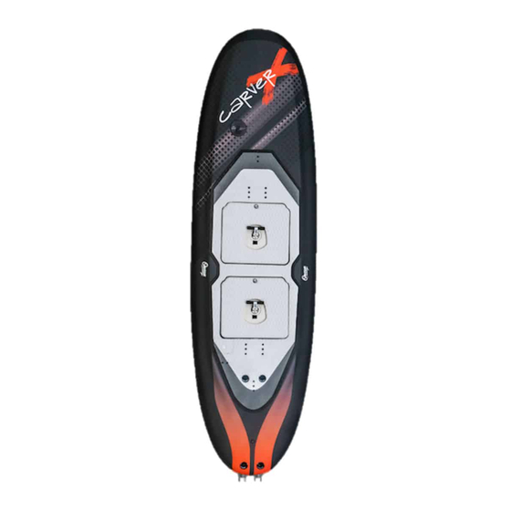
index 1. M .............. 5 5. S ecurity heckS aFety uideLineS 5.1. t ................18 erms of 2. P acking 5.2. b ..........18 efore getting into the Water 2.1. C ................6 arver board 5.3. f ................19 irst Use 2.2. J ................... -
Page 5: M Ain S Ecurity C Hecks
ecurity heckS 1. M ecurity heckS It is important to get familiar with the board’s security systems before starting enjoying it. Please make sure you use the board following the instructions provided in this manual. • Always check the unit before entering the water. Make sure the board, the safety disconnection system, the batteries and the wireless controller are in good condition. -
Page 6: P Acking L Ist
acking 2. P 2.4. b acking atterieS The following describes a list of the components included with the equipment Short circuit, overcharge and temperature and a description of them. protection. Waterproof. • Type: multicell Litio-Ion • Weight: 14 kg / 30 lbs 2.1. -
Page 7: C Harger
acking 2.7. q 2.11. t i charger For the wireLeSS controLLer ooLing Qi inductive technology charger that • Contains conventional manual tools. simplifies charging into just setting your • Screw set and custom made tools necessary for controller down on the charging pad. impeller extraction/insertion. -
Page 8: F Irst Assembly
irst ssembly 3.1. i 3.2. i nSert the FinS nStaLL the LeaSh 1. Insert the fin inside the finbox as shown in the picture. Leash insert 1. Insert the screw through the insert and hold the leash. 2. Insert metallic square 2. -
Page 9: I Nsert The Battery Magnet
irst ssembly 3.3. i 3.4. P nSert the battery Magnet oSitioning the ootStraPS Before using the unit for the first time, the cylindrical magnet must be The board incorporates inserts valid for both goofy and regular riders. inserted in the hole inside the battery compartment. Battery magnet Footstraps inserts... -
Page 10: Se And Configuration Of The Equipment
se and onfigUration of the qUipment 4.1. b atterieS • Do not transport the batteries inside the board unless you intend to 4.1.1. t ranSPort and Storage oF batterieS use it inmediately. Always use the side handle to transport the battery •... - Page 11 Se and onFiguration oF the quiPMent Battery Board Compartment Connectors 3. Make sure the four pins are not visible and be aware of the positioning while inserting it. Only one way is possible according to its geometry. 4. Once the Battery is inserted in the board, insert the four pins to lock the Battery.
-
Page 12: B Attery Charge
se and onfigUration of the qUipment 4.1.3 b attery harge onnection 1. In order to charge the battery it must be taken out from the board. Frontal View 2. Insert the connector to the battery respecting the colors as shown in the previous drawing (red with red and black with black). -
Page 13: B ) Disconnection
Se and onFiguration oF the quiPMent Connector 4.2. w body iSconnection ireLeSS ontroLLer Cable Avoid pulling from the cable, always pull To activate the board you must press on the drop. The power of the Jet will from the connector body. depend on the amount of pressure done on the drop. -
Page 14: Ynchronization
se and onfigUration of the qUipment on the controller beings to blink. At LEDs Power [W] Display this moment, the LED bar will begin to progressively light up. Each position 1 LEDs 1.500 represents different function. SYNC BATTERY 2 LEDs 2.300 LED Blinking 3 LEDs... - Page 15 Se and onFiguration oF the quiPMent • 2 LEDs: Staggered 2. This profile has three power levels. The • 4 LEDs: 100%/0%. The jet will from 0 to 100% power first one allows us to activate the jet at a low power in order to go at by pressing on the drop.
-
Page 16: D ) R Eset
se and onfigUration of the qUipment 4.2.2 . c eSet LedS Linking harging the controLLer 1. Connect the Qi charger through a USB. 2. Place the controller on the center of the Qi as shown in the drawing below. 3. When charging, the green LED will begin to blink. 3. -
Page 17: L Eash
Se and onFiguration oF the quiPMent 4.3. L 4.4. S eaSh ecurity echaniSMS The board has various security mechanisms that stop it automatically in case 1. Attach the leash right below the knee of the front leg, as shown on the drawing below. -
Page 18: Uidelines Afety G Uidelineuidelines
afety uidelineS 5.1 t 5.2. b erMS oF eFore getting into the water • The Carver board is suitable for fresh ans salt water use. Ideal conditions • Make sure the leash and the magnetic security key (kill switch) are in good are with no wind and flat water. -
Page 19: F Irst Use
afety uidelineS 5.3. F 5.4. g irSt uSe etting out oF the water 5.3.1. S • Do not activate the jet outside of the water. The propulsion system is tart uP not meant to be used outside of the water, this could significantly damage During first uses it is recommendable to use it on your knees. -
Page 20: G Eneral Security Measures
afety uidelineS 5.5. g eneraL ecurity eaSureS • This board could reach high speeds. It is recommendable to use a life vest and a helmet while operating this product. • Do not go further off shore than you can return swimming and always have someone watching from shore. -
Page 21: M Aintenance Of The E Quipment
aintenance of the quipMent 6.1. b 6.2. b oard aintenance attery aintenance • It is recommended to rinse the jet with fresh water after every use. • It is crucial to handle the batteries correctly while having it outside When using in extreme saline environments, it´s recommendable to flash of the board. -
Page 22: W Ireless Controller Maintenance
aintenance of the quipMent 6.3. w ireLeSS ontroLLer aintenance • Do not leave the wireless controller exposed to direct sunlight. It has a lithium battery inside and it is advisable not to overheat. • After use, rinse the wireless controller with fresh water and let it dry. it is important to take the controller out of the cover in order to avoid deterioration during storage caused by humidity. -
Page 23: I Mpeller
epaiRs and eplacements Impeller tool rePair and rePLaceMent oF coMPonentS Impeller tooling kit Clean the board with fresh water after every use. Introduce grease into the Impeller tool (7) stator bearings through the greasing screw periodically. Keep the battery Impeller tool (7) power connectors dry and clean. -
Page 24: Ounting The Impeller
epaiRs and eplacements 7.1.2. M ounting the iMPeLLer 1. Hold the tool (7) next 2. Manually introduce the 4. Pass assembly 6. Once the Impeller reaches 8. In order to mount the to the impeller (A)and assembly 1 to the Jet Unit through the tool’s (7) hole the end of its trayectory, Stator/Nozzle assembly... -
Page 25: C Onnectors
WEIGHT: 0,000 kg SIZE DWG NO Surface Finish Onean FILE NAME: WaterPump_montaje Impeller.dft SCALE: 1: 1 SHEET 2 OF 4 The content of this drawing and the intellectual property are property of Aquila Boards S.L.U ( Avda. de la Ribera de Axpe nº11B Mod 210, 48950 Erandio, Bizkaia, Spain), and can't be reproduced or used without their explicit written consent... - Page 26 We´re here to help www.onean.com | support@onean.com @oneanboards fb.me/oneanboards @oneanboards...
Need help?
Do you have a question about the Carver X and is the answer not in the manual?
Questions and answers