Balluff MICROPULSE+ BTL7-A501-M Series User Manual
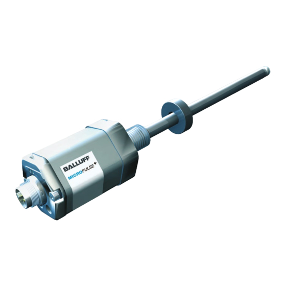
Micropulse transducer - rod style
Hide thumbs
Also See for MICROPULSE+ BTL7-A501-M Series:
- User manual (160 pages) ,
- User manual (120 pages) ,
- User manual (24 pages)
Table of Contents
Advertisement
Quick Links
Download this manual
See also:
User Manual
Advertisement
Table of Contents

Related Manuals for Balluff MICROPULSE+ BTL7-A501-M Series


Summary of Contents for Balluff MICROPULSE+ BTL7-A501-M Series
- Page 1 BTL7-A/E501-M_ _ _ _-A/B/Y/Z(8)-S32/S115/S140 BTL7-A/E501-M_ _ _ _-A/B/Y/Z(8)-KA_ _/FA_ _ User’s Guide english...
- Page 2 www.balluff.com...
-
Page 3: Table Of Contents
Adjust with the calibration device (not with BTL7-...-S140) Calibration device Calibration procedure notes Calibration procedure overview 7.3.1 Teach-in 7.3.2 Adjust 7.3.3 Reset Teach-in with the calibration device Adjust with the calibration device Reset all values with the calibration device (reset) www.balluff.com english... - Page 4 BTL7-A/E501-M_ _ _ _-A/B/Y/Z(8)-S32/S115/S140/KA_ _/FA_ _ Micropulse Transducer - Rod Style Technical data 11.1 Accuracy 11.2 Ambient conditions 11.3 Supply voltage (external) 11.4 Output 11.5 Communication lines La, Lb 11.6 Dimensions, weights Accessories 12.1 Magnets 12.2 Mounting nut 12.3 Connectors and cables 12.3.1 BKS-S32/S33M-00, freely configurable 12.3.2 BKS-S232/S233-PU-_ _, preassembled 12.3.3 BKS-S115/S116-PU-_ _, preassembled...
-
Page 5: Notes To The User
Maximum length: – BTL7-…-A/B/Y/Z-…: 300 mm (500 mm when supported at the end of the rod using slide bush BAM PC-TL-001-D10,4-4 in bore with a diameter of max. 13 mm) Not for BTL7-...-S140 www.balluff.com english... -
Page 6: Safety
The warnings used here contain various signal words and specifications in the technical data is ensured only when are structured as follows: using original BALLUFF accessories, use of any other components will void the warranty. SIGNAL WORD Hazard type and source... -
Page 7: Construction And Function
The transducers with Ø 10.2 mm have an additional thread at the end of the rod to support larger nominal lengths. Calibration device: Additional device for calibrating the transducer (not with BTL7-...-S140). www.balluff.com english... -
Page 8: Function
BTL7-A/E501-M_ _ _ _-A/B/Y/Z(8)-S32/S115/S140/KA_ _/FA_ _ Micropulse Transducer - Rod Style Construction and function (continued) Function LED display The Micropulse Transducer contains the waveguide which LED 1 LED 2 is protected by an outer stainless steel tube (rod). A magnet is moved along the waveguide. This magnet is connected to the system part whose position is to be determined. -
Page 9: Installation And Connection
Mounting hole 3/4"-16UNF per SAE J475 O-ring 15.3x2.4 10.2 mm At least 13 mm 8 mm At least 11 mm Magnet: Various magnets are available for the BTL7 transducer (see Accessories on page 26). Tab. 4-1: Bore diameter if installed in a hydraulic cylinder www.balluff.com english... -
Page 10: Installing The Transducer
BTL7-A/E501-M_ _ _ _-A/B/Y/Z(8)-S32/S115/S140/KA_ _/FA_ _ Micropulse Transducer - Rod Style Installation and connection (continued) Installing the transducer The slide element can be screwed on or bonded. Secure the screws so they cannot be loosened or lost. Select a suitable adhesive. NOTICE! Slide surface Interference in function... -
Page 11: Electrical Connection
Tab. 4-3: Connection assignment BTL7...S115 Unassigned leads can be connected to the GND on the controller side but not to the shield. Factory setting, can be freely configured with the PC software. Reference potential for supply voltage and EMC-GND. www.balluff.com english... -
Page 12: Connector S140
BTL7-A/E501-M_ _ _ _-A/B/Y/Z(8)-S32/S115/S140/KA_ _/FA_ _ Micropulse Transducer - Rod Style Installation and connection (continued) 4.4.3 Connector S140 S140 BTL7-... interface -A501 -E501 Not used 4 to 20 mA (output 1) Fig. 4-11: Pin assignment of S140 (view of connector pins of transducer), 10 to 0 V (output 2) 20 to 4 mA... -
Page 13: Startup
Operating notes – Check the function of the transducer and all associated components on a regular basis. – Take the position measuring system out of operation whenever there is a malfunction. – Secure the system against unauthorized use. www.balluff.com english... -
Page 14: Configuration With The Micropulse Configuration Tool
Resetting to factory settings is possible – Demo mode without having transducer connected Configuration options The PC software and associated manual can Prerequisites be found in the Internet under www.balluff.com/ – USB communication box connected to the transducer downloads-btl7. and PC. –... - Page 15 This could result in personal injury and equipment damage. The system must be taken out of operation before configuration. Transducers may only be connected to the communication box for configuration. The communication box must be removed after configuration. www.balluff.com english...
-
Page 16: Adjust With The Calibration Device (Not With Btl7
BTL7-A/E501-M_ _ _ _-A/B/Y/Z(8)-S32/S115/S140/KA_ _/FA_ _ Micropulse Transducer - Rod Style Adjust with the calibration device (not with BTL7-...-S140) Calibration device Automatic deactivation! If the buttons on the calibration device are not The calibration device is an additional device for calibrating pressed for approx. 10 min, programming the transducer if configuration with a PC and software is mode is automatically ended. -
Page 17: Calibration Procedure Overview
2 is changed to a rising curve. New null point Before After Fig. 7-2: Reading new null point Move magnet to the new end position. Read new end point by pressing the buttons. The current null point remains the same. www.balluff.com english... -
Page 18: Adjust
BTL7-A/E501-M_ _ _ _-A/B/Y/Z(8)-S32/S115/S140/KA_ _/FA_ _ Micropulse Transducer - Rod Style Adjust with the calibration device (continued) Move magnet to the new end position. 7.3.2 Adjust Read new end point by pressing the buttons. The detailed procedure for adjustment is Set the new end value by pressing the buttons. -
Page 19: Teach-In With The Calibration Device
Any of the individual steps for settings can be selected. The teach-in process can be ended at any time. LED legend: LED not on LED green LED 1 and LED 2 flashing green-green in LED red alternation www.balluff.com english... -
Page 20: Adjust With The Calibration Device
BTL7-A/E501-M_ _ _ _-A/B/Y/Z(8)-S32/S115/S140/KA_ _/FA_ _ Micropulse Transducer - Rod Style Adjust with the calibration device NOTICE! Interference in function LED display Displayed values (example) Adjustment while the system is running may result in malfunctions. LED1 LED2 At 0 to 10 V At 4 to 20 mA Stop the system before performing adjustment. - Page 21 1 mV or 1 A. If a button is held down longer than 1 s, the step LED green LED 1 and LED 2 flashing red-green in alternation interval is increased. LED 1 and LED 2 flashing red-red in alternation www.balluff.com english...
- Page 22 BTL7-A/E501-M_ _ _ _-A/B/Y/Z(8)-S32/S115/S140/KA_ _/FA_ _ Micropulse Transducer - Rod Style Adjust with the calibration device (continued) Switch the output to be adjusted (optional) As standard, the values are adjusted at output 1 and the values at output 2 are inverted accordingly. LED display Displayed values (example) From serial number 100503000xxxxx xx, it is...
-
Page 23: Reset All Values With The Calibration Device (Reset)
Activate reset step. Briefly press simultaneously (< 1 s). < 1 s Release buttons. Current position value is displayed. LED legend: LED not on LED green LED flashing green-red LED 1 and LED 2 flashing green-red simultaneously www.balluff.com english... -
Page 24: Technical Data
: Use in enclosed spaces and up to a height of 2000 m above sea Relative humidity < 90%, non-condensing level. Rod pressure rating (when Individual specifications as per Balluff factory standard installed in hydraulic cylinders) : The transducer must be externally connected via a limitedenergy For Ø 8 mm < 250 bar circuit as defined in UL 61010-1, a low-power source as defined in For Ø 10.2 mm... -
Page 25: Dimensions, Weights
Max. 7 mm Permissible bending radius Fixed routing ≥ 35 mm Movable ≥ 105 mm BTL7-...-FA_ _ Cable material PTFE No UL approval available Cable temperature –55°C to +200°C Cable diameter Max. 7 mm Permissible bending radius Fixed routing ≥ 35 mm Movable No permissible bending radius www.balluff.com english... -
Page 26: Accessories
BTL7-A/E501-M_ _ _ _-A/B/Y/Z(8)-S32/S115/S140/KA_ _/FA_ _ Micropulse Transducer - Rod Style Accessories Accessories are not included in the scope of delivery and BTL-P-1013-4R, BTL-P-1013-4S, BTL-P-1012-4R, must be ordered separately. BTL-P-1014-2R: Weight: Approx. 10 g 12.1 Magnets Housing: Anodized aluminum BTL-P-1013-4R Included in the scope of delivery for the BTL-P-1013-4R, BTL-P-1013-4S, BTL-P-1012-4R: Spacer: 8 mm, material: polyoxymethylene... -
Page 27: Connectors And Cables
Ø 20 Fig. 12-6: Connector BKS-S233-PU-_ _ Fig. 12-4: Connector BKS-S33M-00 The outlet direction and the pin assignment for the BKS-S233-PU-_ _ is the same as that for the BKS S116-PU-_ _ (sea Fig. 12-9 or Tab. 12-1). www.balluff.com english... -
Page 28: Bks-S115/S116-Pu
BTL7-A/E501-M_ _ _ _-A/B/Y/Z(8)-S32/S115/S140/KA_ _/FA_ _ Micropulse Transducer - Rod Style Accessories (continued) 12.3.3 BKS-S115/S116-PU-_ _, preassembled 12.3.4 BKS-S140-23-00, freely configurable BKS-S115-PU-_ _ BKS-S140-23-00 Straight connector, molded-on cable, preassembled Straight connector, freely configurable M12, 8-pin 10-pin Various cable lengths can be ordered, e.g. BKS-S115-PU-05: Cable length 5 m Fig. -
Page 29: Usb Communication Box
For BTL7-A/E501-... with S140 connector. Scope of delivery: USB communication box, USB cable, 2 adapter cables each approx. 0.3 m, condensed guide. BTL7-A-CB01-USB-KA For BTL7-A/E501-... with cable connection Scope of delivery: USB communication box, USB cable, 1 adapter cable approx. 0.6 m, condensed guide. www.balluff.com english... -
Page 30: Type Code Breakdown
BTL7-A/E501-M_ _ _ _-A/B/Y/Z(8)-S32/S115/S140/KA_ _/FA_ _ Micropulse Transducer - Rod Style Type code breakdown BTL7 - A 5 0 1 - M0500 - B - S32 Micropulse transducer Interface: A = Analog interface, voltage output 0 to 10 V (Factory setting) E = Analog interface, current output 4 to 20 mA (Factory setting) Supply voltage: 5 = 10 to 30 V DC... -
Page 31: Appendix
0.27559055 0.31496063 0.35433071 0.393700787 Tab. 14-1: Conversion table mm to inches Ordering code Type Serial number 1 inch = 25.4 mm Fig. 14-1: BTL7 part label inches 25.4 50.8 76.2 101.6 152.4 177.8 203.2 228.6 Tab. 14-2: Conversion table inches to mm www.balluff.com english...
Need help?
Do you have a question about the MICROPULSE+ BTL7-A501-M Series and is the answer not in the manual?
Questions and answers