Sign In
Upload
Manuals
Brands
Balluff Manuals
Measuring Instruments
MICROPULSE+ BTL7-A501-M Series
Balluff MICROPULSE+ BTL7-A501-M Series Manuals
Manuals and User Guides for Balluff MICROPULSE+ BTL7-A501-M Series. We have
4
Balluff MICROPULSE+ BTL7-A501-M Series manuals available for free PDF download: User Manual
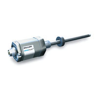
Balluff MICROPULSE+ BTL7-A501-M Series User Manual (160 pages)
Brand:
Balluff
| Category:
Transducer
| Size: 13.46 MB
Table of Contents
Deutsch
3
Table of Contents
3
Verwendete Symbole und Konventionen
5
Lieferumfang
5
Zulassungen und Kennzeichnungen
5
Benutzerhinweise
5
Sicherheit
6
Bestimmungsgemäße Verwendung
6
Allgemeines zur Sicherheit des Wegmesssystems
6
Bedeutung der Warnhinweise
6
Entsorgung
6
Aufbau und Funktion
7
Aufbau
7
Funktion
8
LED-Anzeige
8
Einbau und Anschluss
9
Einbauvarianten
9
Einbau Vorbereiten
9
Wegaufnehmer Einbauen
10
Einbauempfehlung für Hydraulikzylinder
10
Elektrischer Anschluss
11
Steckverbinder S32/Kabelanschluss
11
Steckverbinder S115
11
Steckverbinder S140
12
Schirmung und Kabelverlegung
12
Inbetriebnahme
13
System in Betrieb Nehmen
13
Hinweise zum Betrieb
13
Konfiguration mit dem Micropulse Configuration Tool
14
Micropulse Configuration Tool
14
Anschluss der USB-Kommunikationsbox
14
Konfigurationsmöglichkeiten
14
Einstellen mit der Einstellvorrichtung (nicht bei BTL7
16
Einstellvorrichtung
16
Hinweise zum Einstellvorgang
16
Übersicht der Einstellverfahren
17
Justieren
18
Teach-In mit der Einstellvorrichtung
19
Justieren mit der Einstellvorrichtung
20
Rücksetzen aller Werte mit der Einstellvorrichtung (Reset)
23
Technische Daten
24
Maße, Gewichte
25
Zubehör
26
11
27
12
27
Steckverbinder und Kabel
27
Bks-S115/S116-Pu
28
Www.balluff.com Deutsch
29
Typenschlüssel
30
13
31
Anhang
31
Español
67
Eliminación de Desechos
70
Estructura y Funcionamiento
71
Generalidades sobre la Seguridad del Sistema de Medición de Desplazamiento
70
Seguridad
70
Significado de las Advertencias
70
Uso Debido
70
Funcionamiento
72
Indicador LED
72
Montaje y Conexión
73
Preparación del Montaje
73
Variantes de Montaje
73
Montaje del Transductor de Desplazamiento
74
Recomendación de Montaje para Cilindros Hidráulicos
74
Conexión Eléctrica
75
Conector S32/Conexión de Cable
75
Conector S115
75
Conector S140
76
Blindaje y Tendido de Cables
76
Indicaciones sobre el Servicio
77
Configuración con la Micropulse Configuration Tool
78
Puesta en Servicio del Sistema
77
Conexión del Módulo de Comunicación USB
78
Micropulse Configuration Tool
78
Posibilidades de Configuración
78
Ajuste con el Dispositivo de Ajuste (no con BTL7
80
Dispositivo de Ajuste
80
Indicaciones Acerca del Proceso de Ajuste
80
Vista General de Los Procedimientos de Ajuste
81
Aprendizaje
81
Ajuste
82
Reset
82
Aprendizaje con el Dispositivo de Ajuste
83
Ajuste de Valores con el Dispositivo de Ajuste
84
Reposición de todos Los Valores con el Dispositivo de Ajuste (Reset)
87
Datos Técnicos
88
11
88
Precisión
88
Condiciones Ambientales
88
Alimentación de Tensión (Externa)
88
Salida
88
Líneas de Comunicación La, Lb
88
Medidas, Pesos
89
Accesorios
90
12
90
Sensores de Posición
90
Tuerca de Fijación
90
Conectores y Cables
91
12.3.1 BKS-S32/S33M-00, Libremente Confeccionable
91
Bks-S232/S233-Pu
91
Bks-S115/S116-Pu
92
12.3.4 BKS-S140-23-00, Libremente Confeccionable
92
12.3.5 Sistema Enchufable, 8 Polos
92
13
95
Módulo de Comunicación USB
93
Código de Modelo
94
Anexo
95
14
95
Conversión de Unidades de Longitud
95
Placas de Características
95
Français
99
Conditionnement
101
Sécurité
102
Elimination
102
Généralités Sur la Sécurité du Système de Mesure de Déplacement
102
Signification des Avertissements
102
Utilisation Conforme Aux Prescriptions
102
Fonction
103
Affichage À LED
104
Montage Et Raccordement
105
Préparation du Montage
105
Variantes de Montage
105
Montage du Capteur de Déplacement
106
Recommandation de Montage Pour Vérin Hydraulique
106
Raccordement Électrique
107
Connecteur S32 / Raccordement du Câble
107
Connecteur S115
107
Connecteur S140
108
Mise en Service
109
13 5.2 Conseils D'utilisation
109
Mise en Service du Système
109
Configuration Avec Micropulse Configuration Tool
110
Micropulse Configuration Tool
110
Possibilités de Configuration
110
Réglage À L'aide du Dispositif de Réglage (Sauf Pour BTL7
112
Raccordement du Module de Communication USB
110
Dispositif de Réglage
112
Remarques Concernant la Procédure de Réglage
112
Advertisement
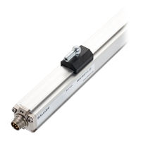
Balluff MICROPULSE+ BTL7-A501-M Series User Manual (120 pages)
Brand:
Balluff
| Category:
Transducer
| Size: 4.8 MB
Table of Contents
Deutsch
3
Table of Contents
3
Zulassungen und Kennzeichnungen
5
Verwendete Symbole und Konventionen
5
Lieferumfang
5
Sicherheit
6
Bestimmungsgemäße Verwendung
6
Allgemeines zur Sicherheit des Wegmesssystems
6
Bedeutung der Warnhinweise
6
Entsorgung
6
Aufbau und Funktion
7
Funktion
8
LED Anzeige
8
Einbau und Anschluss
9
Wegaufnehmer Einbauen
9
Geführte Positionsgeber
9
Freie Positionsgeber
10
Steckverbinder S115
11
Steckverbinder S32/Kabelanschluss KA
11
Elektrischer Anschluss
11
Schirmung und Kabelverlegung
12
Inbetriebnahme
13
System in Betrieb Nehmen
13
Hinweise zum Betrieb
13
Konfiguration mit dem Micropulse Configuration Tool
14
Wertetabelle für Werkseinstellung
14
Micropulse Configuration Tool
14
Anschluss der USB-Kommunikationsbox
14
Konfigurationsmöglichkeiten
15
Technische Daten
16
Genauigkeit
16
Umgebungsbedingungen
16
Spannungsversorgung (Extern)
16
Ausgang
16
Kommunikationsleitungen La, Lb
17
Maße, Gewichte
17
Gelenkstange BTL2-GS10
18
Zubehör
18
Geführte Positionsgeber
18
Freie Positionsgeber
19
Steckverbinder und Kabel
20
BKS-S32/S33M-00, Frei Konfektionierbar
20
Bks-S232/S233-Pu
20
Bks-S115/S116-Pu
21
USB-Kommunikationsbox
21
English
27
Approvals and Markings
29
Scope of Delivery
29
Symbols and Conventions
29
Disposal
30
Explanation of the Warnings
30
General Safety Notes for the Position Measuring System
30
Intended Use
30
Safety
30
Construction and Function
31
Function
32
LED Display
32
Captive Magnets
33
Installation and Connection
33
Installing the Transducer
33
Floating Magnets
34
Connector S115
35
Connector S32/Cable Connection KA
35
Electrical Connection
35
Shielding and Cable Routing
36
Operating Notes
37
Starting up the System
37
Startup
37
Configuration with the Micropulse Configuration Tool
38
Connecting the USB Communication Box
38
Micropulse Configuration Tool
38
Value Table for Factory Setting
38
Configuration Options
39
Ambient Conditions
40
Output
40
Supply Voltage (External)
40
Technical Data
40
Communication Lines La, Lb
41
Dimensions, Weights
41
Accessories
42
Btl2-Gs10
42
Captive Magnets
42
Bks-S232/S233-Pu
44
BKS-S32/S33M-00, Freely Configurable
44
Bks-S115/S116-Pu
45
USB Communication Box
45
Español
51
Desplazamiento
53
Eliminación de Desechos
54
Significado de las Advertencias
54
Estructura y Funcionamiento
55
Funcionamiento
56
Indicador LED
56
Montaje del Transductor de Desplazamiento
57
Montaje y Conexión
57
Sensores de Posición Guiados
57
Sensores de Posición Libres
58
Conector S115
59
Conector S32/Conexión de Cable KA
59
Conexión Eléctrica
59
Blindaje y Tendido de Cables
60
Indicaciones sobre el Servicio
61
Puesta en Servicio
61
Puesta en Servicio del Sistema
61
Conexión del Módulo de Comunicación USB
62
Configuración con la Micropulse Configuration Tool
62
Micropulse Configuration Tool
62
Tabla de Valores del Ajuste de Fábrica
62
Posibilidades de Configuración
63
Alimentación de Tensión (Externa)
64
Condiciones Ambientales
64
Datos Técnicos
64
Salida
64
Líneas de Comunicación La, Lb
65
Medidas, Pesos
65
Accesorios
66
Sensores de Posición Guiados
66
Varilla Articulada BTL2-GS10
66
Français
75
Conditionnement
77
Elimination
78
Sécurité
78
Utilisation Conforme Aux Prescriptions
78
Structure Et Fonction
79
Fonction
80
Montage du Capteur de Déplacement
81
Montage Et Raccordement
81
Connecteur S115
83
Connecteur S32 / Raccordement du Câble KA
83
Raccordement Électrique
83
Blindage Et Pose des Câbles
84
Mise en Service
85
Mise en Service du Système
85
Configuration Avec Micropulse Configuration Tool
86
Micropulse Configuration Tool
86
Raccordement du Module de Communication USB
86
Tableau de Valeurs du Réglage Usine
86
Possibilités de Configuration
87
Alimentation Électrique (Externe)
88
Caractéristiques Techniques
88
Sorties
88
Câbles de Communication la Et Lb
89
Dimensions, Poids
89
Capteurs de Position Guidés
90
Tige Articulée BTL2-GS10
90
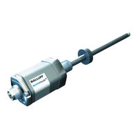
Balluff MICROPULSE+ BTL7-A501-M Series User Manual (31 pages)
Micropulse Transducer - Rod Style
Brand:
Balluff
| Category:
Measuring Instruments
| Size: 0.66 MB
Table of Contents
Table of Contents
3
Approvals and Markings
5
Note to the User
5
Safety
6
Notes to the User
5
Scope of Delivery
5
Symbols and Conventions
5
Validity
5
Disposal
6
Construction and Function
7
General Safety Notes for the Position Measuring System
6
Intended Use
6
Meaning of the Warnings
6
Construction
7
Function
8
LED Display
8
Installation and Connection
9
Installation Variants
9
Preparing for Installation
9
Installing the Transducer
10
Installation Recommendation for Hydraulic Cylinders
10
Electrical Connection
11
Connector S32/Cable Connection
11
Connector S115
11
Connector S140
12
Shielding and Cable Routing
12
Startup
13
Operating Notes
13
Configuration with the Micropulse Configuration Tool
14
Starting up the System
13
Configuration Options
14
Adjust with the Calibration Device (Not with BTL7
16
Connecting the USB Communication Box
14
Micropulse Configuration Tool
14
Calibration Device
16
Calibration Procedure Notes
16
Calibration Procedure Overview
17
Teach-In
17
Adjust
18
Reset
18
Teach-In with the Calibration Device
19
Adjust with the Calibration Device
20
Reset All Values with the Calibration Device (Reset)
23
Technical Data
24
Accuracy
24
Ambient Conditions
24
Communication Lines La, Lb
24
Output
24
Supply Voltage (External)
24
Dimensions, Weights
25
Accessories
26
Magnets
26
Mounting Nut
26
Connectors and Cables
27
12.3.1 BKS-S32/S33M-00, Freely Configurable
27
Bks-S232/S233-Pu
27
Bks-S115/S116-Pu
28
12.3.4 BKS-S140-23-00, Freely Configurable
28
12.3.5 Plug-In System, 8-Pin
28
USB Communication Box
29
Type Code Breakdown
30
Appendix
31
Converting Units of Length
31
Part Labels
31
Advertisement
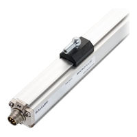
Balluff MICROPULSE+ BTL7-A501-M Series User Manual (24 pages)
Brand:
Balluff
| Category:
Industrial Equipment
| Size: 1.38 MB
Table of Contents
Table of Contents
3
Notes to the User
5
Symbols and Conventions
5
Scope of Delivery
5
Approvals and Markings
5
Safety
6
Intended Use
6
General Safety Notes for the Position Measuring System
6
Explanation of the Warnings
6
Disposal
6
Construction and Function
7
Function
8
LED Display
8
Installation and Connection
9
Installing the Transducer
9
Captive Magnets
9
Floating Magnets
10
Electrical Connection
11
Connector S32/Cable Connection KA
11
Connector S115
11
Shielding and Cable Routing
12
Startup
13
Starting up the System
13
Operating Notes
13
Configuration with the Micropulse Configuration Tool
14
Value Table for Factory Setting
14
Micropulse Configuration Tool
14
Connecting the USB Communication Box
14
Configuration Options
15
Technical Data
16
Accuracy
16
Ambient Conditions
16
Supply Voltage (External)
16
Output
16
Communication Lines La, Lb
16
Dimensions, Weights
17
Accessories
18
Captive Magnets
18
Btl2-Gs10
18
Floating Magnets
19
Connectors and Cables
20
BKS-S32/S33M-00, Freely Configurable
20
Bks-S232/S233-Pu
20
Bks-S115/S116-Pu
21
USB Communication Box
21
Advertisement
Related Products
Balluff MICROPULSE+ BTL7-E501-M Series
Balluff BFT Series
Balluff BML-S1G0-Q71 Series
Balluff BAM021H
Balluff BLA0007
Balluff BTL7-A501 Series
Balluff BTL7-A501-M0500-P-S32
Balluff BTL7-A505-M Series
Balluff BTL7-A50 Series
Balluff BTL7-A501-M-P-S32/KA Series
Balluff Categories
Accessories
Transducer
Industrial Equipment
Switch
Rfid Systems
More Balluff Manuals
Login
Sign In
OR
Sign in with Facebook
Sign in with Google
Upload manual
Upload from disk
Upload from URL