Table of Contents
Advertisement
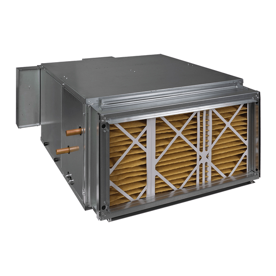
Installation, Start-Up, and Service Instructions
CONTENTS
SAFETY CONSIDERATIONS . . . . . . . . . . . . . . . . . . . 1
AHRI Certification . . . . . . . . . . . . . . . . . . . . . . . . . . . . 2
C-ETL-US Listing . . . . . . . . . . . . . . . . . . . . . . . . . . . . . 2
Introduction . . . . . . . . . . . . . . . . . . . . . . . . . . . . . . . . . 2
PRE-INSTALLATION . . . . . . . . . . . . . . . . . . . . . . . . . . 3
Unpacking and Inspection . . . . . . . . . . . . . . . . . . . . . 3
Prepare Job Site for Unit Installation . . . . . . . . . . . . 3
Identify and Prepare Units . . . . . . . . . . . . . . . . . . . . . 3
Protect Units from Damage . . . . . . . . . . . . . . . . . . . . 3
INSTALLATION . . . . . . . . . . . . . . . . . . . . . . . . . . . . . . 3
Step 1 - Place Unit In Position . . . . . . . . . . . . . . . . . 3
Step 2 - Install Mixing Box . . . . . . . . . . . . . . . . . . . . 5
Step 3 - Connect Cooling/Heating Piping . . . . . . . . 7
Step 4 - Make Electrical Connections . . . . . . . . . . 12
Step 5 - Connect Ductwork . . . . . . . . . . . . . . . . . . 12
Step 6 - Make Final Preparations . . . . . . . . . . . . . 13
START-UP . . . . . . . . . . . . . . . . . . . . . . . . . . . . . . . . . 13
Cooling/Heating System . . . . . . . . . . . . . . . . . . . . . . 13
Air Balance System . . . . . . . . . . . . . . . . . . . . . . . . . . 14
Motor/Blower Assembly . . . . . . . . . . . . . . . . . . . . . . 14
Electronically Commutated Motor (ECM) . . . . . . . . 14
Control Board Adjustment . . . . . . . . . . . . . . . . . . . . 14
Water Balancing System . . . . . . . . . . . . . . . . . . . . . 15
Water Treatment . . . . . . . . . . . . . . . . . . . . . . . . . . . . 16
SERVICE . . . . . . . . . . . . . . . . . . . . . . . . . . . . . . . . . . 16
General . . . . . . . . . . . . . . . . . . . . . . . . . . . . . . . . . . . . 16
Coils . . . . . . . . . . . . . . . . . . . . . . . . . . . . . . . . . . . . . . 16
Electric Resistance Heater Assembly . . . . . . . . . . . 16
Cabinet/Control Box Maintenance Light . . . . . . . . . 17
Electrical Wiring and Controls . . . . . . . . . . . . . . . . . 17
Drain . . . . . . . . . . . . . . . . . . . . . . . . . . . . . . . . . . . . . . 17
Filters - Throwaway . . . . . . . . . . . . . . . . . . . . . . . . 17
Filters - Replacement and Installation . . . . . . . . . 17
EXAMPLES . . . . . . . . . . . . . . . . . . . . . . . . . . . . . . 19
START-UP CHECKLIST . . . . . . . . . . . . . . . . . . . . . CL-1
SAFETY CONSIDERATIONS
Improper installation, adjustment, alteration, service, mainte-
nance, or use can cause explosion, fire, electrical shock or oth-
er conditions which may cause personal injury or property
damage. Consult a qualified installer, service agency, or your
distributor or branch for information or assistance. The quali-
fied installer or agency must use factory-authorized kits or ac-
cessories when modifying this product. Refer to the individual
Manufacturer reserves the right to discontinue, or change at any time, specifications or designs without notice and without incurring obligations.
Catalog No. 04-53420019-01
Horizontal Direct Drive Blower Fan
PAGE
Printed in U.S.A.
Form 42DH-2SI
instructions packaged with the kits or accessories when
installing.
Follow all safety codes. Wear safety glasses and work gloves.
Use quenching cloths for brazing operations and have a fire ex-
tinguisher available. Read these instructions thoroughly and
follow all warnings or cautions attached to the unit. Consult lo-
cal building codes and appropriate national electrical codes (in
USA, ANSI/NFPA 70, National Electrical Code (NEC); in
Canada, CSA C22.1) for special requirements.
It is important to recognize safety information. This is the safe-
ty-alert symbol
. When you see this symbol on the unit and
in instructions or manuals, be alert to the potential for personal
injury.
Understand the signal words DANGER, WARNING, CAU-
TION, and NOTE. These words are used with the safety-alert
symbol. DANGER identifies the most serious hazards which
will result in severe personal injury or death. WARNING signi-
fies hazards which could result in personal injury or death.
CAUTION is used to identify unsafe practices, which may re-
sult in minor personal injury or product and property damage.
NOTE is used to highlight suggestions which will result in en-
hanced installation, reliability, or operation.
WARNING
ELECTRICAL SHOCK HAZARD
Failure to follow this warning could cause personal injury
or death.
Before performing service or maintenance operations on
unit, always turn off main power switch to unit and install
lock(s) and lockout tag(s). Unit may have more than one
power switch.
CAUTION
CUT HAZARD
Sheet metal parts may have sharp edges or burrs. Use care
and wear appropriate protective clothing, safety glasses and
gloves when handling parts and servicing air-conditioning
equipment.
Equipment is initially protected under the manufacturer's stan-
dard warranty; however, this warranty is provided under the
condition that the steps outlined in this manual for initial in-
spection, proper installation, commissioning, regular periodic
maintenance, and everyday operation of the equipment be fol-
lowed in detail. This manual should be fully reviewed and un-
derstood in advance of initial installation, start-up, and any
maintenance. Should any questions arise, please contact your
local Sales Representative or the factory BEFORE proceeding.
Pg 1
42DH 06-30
Coils
8-19
Replaces: 42DH-1SI
Advertisement
Table of Contents

Subscribe to Our Youtube Channel
Related Manuals for Carrier 42DH 06


Summary of Contents for Carrier 42DH 06
-
Page 1: Table Of Contents
42DH 06-30 Horizontal Direct Drive Blower Fan Coils Installation, Start-Up, and Service Instructions instructions packaged with the kits or accessories when CONTENTS installing. PAGE Follow all safety codes. Wear safety glasses and work gloves. SAFETY CONSIDERATIONS ....1 Use quenching cloths for brazing operations and have a fire ex- AHRI Certification . -
Page 2: Ahri Certification
Use a suitable heat shield material to contain C-ETL-US Listing sparks or drops of solder. Have a fire extinguisher readily Carrier’s Direct Drive Series blower coil units are listed by available. Intertek Testing Services (ITS). ITS’s C-ETL-US listing signifies that Carrier’s blower coil units have been examined... -
Page 3: Pre-Installation
Any hidden damage or missing components should be record- proper line size and water supply availability. ed and immediately reported to the carrier and a claim filed. In the event a claim for shipping damage is filed, the unit, ship-... - Page 4 MINIMUM RECOMMENDED 29 IN. DRAIN PAN CLEARANCE FILTER MINIMUM RECOMMENDED CLEARANCE 29 IN. ELECTRIC HEAT ELEMENTS AIRFLOW AIRFLOW ELECTRIC HEAT CONTROLS FAN MOTOR PIPING PACKAGE MINIMUM RECOMMENDED 29 IN. CLEARANCE Fig. 3 — Unit Installation - Recommended Clearances (Top View) The unit must be mounted level.
-
Page 5: Step 2 - Install Mixing Box
Step 2 — Install Mixing Box Mixing boxes are pre-assembled from the factory for ease of installation. A linkage kit consisting of two crank arms, 2 swivels, and either a 25-in. (sizes 06-16) or a 34-in. (sizes 20-30) length of in. - Page 6 INLET AND OUTLET DAMPERS INSTALLATION Install actuator per manufacturer's instructions. Adjust damper shafts outward to extend past any obstacles that might cause interference. Do not adjust inward end of shaft within a distance of 2 inches of bronze bushing. Position inlet damper and outlet damper to coincide with current or intended position of actuator arm, depending on actuator's position (opened/closed).
-
Page 7: Step 3 - Connect Cooling/Heating Piping
2(51) 2(51) TOP VIEWS 4(102) 1(25) 2.4(61) 3(76) 2.4(61) 2.4(61) 3(76) 2.4(61) 1(25) 4(102) BTM/REAR INLET - 42DH TOP/REAR INLET - 42DH DIMENSIONS - INCHES (MILLIMETERS) Unit Size 18.50 (470) (711) (711) (610) (279) 18.50 (470) (711) (711) (610) (279) 20.25 (514) (940) - Page 8 CR - COLD WATER RETURN HR - HOT WATER RETURN CS - COLD WATER SUPPLY HS - HOT WATER SUPPLY RH - RIGHT HAND LH - LEFT HAND COIL HEADER CONNECTION SIZE 8 Row 6 Row 4 Row 2 Row HW 1 Row HW Unit Nom.
- Page 9 HR - HOT WATER RETURN HS - HOT WATER SUPPLY LL - LIQUID LINE SL - SUCTION LINE COIL HEADER CONNECTION SIZE (NOMINAL OD IN INCHES) 2 Row HW 1 Row HW Unit Nom. Nom. Nom. Nom. Size Size Size Size Size 06-12...
- Page 10 Drawing is not to scale and is provided for reference only. Dimensions may vary with options ordered. Aux.Ctrl. Supply Duct Return Duct (Note 7) Mounting Holes Size Depth Width Height Size 9 x 6 (914) (711) (502) (225) (276) (349) (57) (616) (356)
- Page 11 Drawing is not to scale and is provided for reference only. Dimensions may vary with options ordered. Mounting Unit Supply Duct Return Duct (Note 7) Mix Box Aux.Box Size Depth Width Height Holes Size Depth ⁵/ ³/ ⁷/ ⁷/ ³/ ¹/ ¹/ ¹/...
-
Page 12: Step 4 - Make Electrical Connections
LEAK TESTING must be familiar with the wiring diagram and serial plate on the unit BEFORE beginning any wiring. After securing the connections, test the system for any leaks. Always test hydronic systems with water as some components are not designed to be inert gas pressurized. 42DHA20 776004-60-1 Model No:... -
Page 13: Step 6 - Make Final Preparations
Auxillary Control Box Disconnect Switch (supplied when ordered with 3-speed controls Limit Switch Service Light Knob and/or service light) Heater Fuses Strip Electric Heater Service Light Battery 24V Control Fuse Battery Charger Bonded Motor Ground Control Board Wrapper Serial Plate Equipment Door Switch Ground... -
Page 14: Air Balance System
IMPORTANT: The air vent provided on the unit is not CAUTION intended to replace the main system air vents and may not release air trapped in other parts of the system. Inde- Only trained and qualified individuals should attempt to ad- pendently inspect the entire system for potential air traps just or service components on any energized electrical and vent those areas as required. -
Page 15: Water Balancing System
NOTE: For specific voltages adjustment please contact Carrier Each hydronic system has different operating characteristics de- factory representative. pending on the devices and controls used in the system. The ac- tual balancing technique may vary from one system to another. -
Page 16: Water Treatment
Observe and adhere to all safety precautions contained in the preface of this manual during all service and maintenance Carrier water coil tubes and headers are constructed of cop- operations. per. Multiple brass alloys may be present in the valve pack- age. -
Page 17: Cabinet/Control Box Maintenance Light
High-limit thermal switches must be replaced once the circuit familiar with local conditions for chemicals, or other solu- has been broken. The high-limit thermal cutout device is a tions available to control these agents. safety device only, not intended for continuous operation. This Filters —... - Page 18 D - FILTER SUPPORT ANGLE BRACKET 4” FILTER SEE DETAIL X DETAIL X SEE DETAIL Y DETAIL Y 1” FILTER 1” FILTER MOUNTING HOLES MAGNETS 2” FILTER MOUNTING HOLES 2” FILTER Fig. 23 — Filter Rack...
-
Page 19: Appendix A - Typical Wiring Diagram Examples
APPENDIX A — TYPICAL WIRING DIAGRAM EXAMPLES WARNING: Wiring diagrams are provided as an example only, ALWAYS refer to WIRING DIAGRAM attached to the unit! Fig. A — No Electric Heat, Single Phase Power with Control Board WARNING: Wiring diagrams are provided as an example only, ALWAYS refer to WIRING DIAGRAM attached to the unit! Fig. - Page 20 APPENDIX A — TYPICAL WIRING DIAGRAM EXAMPLES (cont) WARNING: Wiring diagrams are provided as an example only, ALWAYS refer to WIRING DIAGRAM attached to the unit! Fig. C — Single Element Heater, Single Stage Heat, Single Phase Power with Control Board WARNING: Wiring diagrams are provided as an example only, ALWAYS refer to WIRING DIAGRAM attached to the unit!
- Page 21 APPENDIX A — TYPICAL WIRING DIAGRAM EXAMPLES (cont) WARNING: Wiring diagrams are provided as an example only, ALWAYS refer to WIRING DIAGRAM attached to the unit! Fig. E — Two Element Heater, Two-Stage Heat, Single Phase Power with Control Board WARNING: Wiring diagrams are provided as an example only, ALWAYS refer to WIRING DIAGRAM attached to the unit!
- Page 22 APPENDIX A — TYPICAL WIRING DIAGRAM EXAMPLES (cont) WARNING: Wiring diagrams are provided as an example only, ALWAYS refer to WIRING DIAGRAM attached to the unit! Fig. G — Six Element Heater, Single Stage Heat, Three Phase Power with Control Board WARNING: Wiring diagrams are provided as an example only, ALWAYS refer to WIRING DIAGRAM attached to the unit!
- Page 23 APPENDIX A — TYPICAL WIRING DIAGRAM EXAMPLES (cont) WARNING: Wiring diagrams are provided as an example only, ALWAYS refer to WIRING DIAGRAM attached to the unit! Fig. I — Nine Element Heater, Single Stage Heat, Three Phase Power with Control Board WARNING: Wiring diagrams are provided as an example only, ALWAYS refer to WIRING DIAGRAM attached to the unit!
- Page 24 APPENDIX A — TYPICAL WIRING DIAGRAM EXAMPLES (cont) WARNING: Wiring diagrams are provided as an example only, ALWAYS refer to WIRING DIAGRAM attached to the unit! Fig. K — Nine Element Heater, Three Stage Heat, Three Phase Power with Control Board WARNING: Wiring diagrams are provided as an example only, ALWAYS refer to WIRING DIAGRAM attached to the unit!
- Page 25 APPENDIX A — TYPICAL WIRING DIAGRAM EXAMPLES (cont) WARNING: Wiring diagrams are provided as an example only, ALWAYS refer to WIRING DIAGRAM attached to the unit! Fig. M — No Electric Heat, Three Phase Power without Control Board WARNING: Wiring diagrams are provided as an example only, ALWAYS refer to WIRING DIAGRAM attached to the unit! Fig.
- Page 26 APPENDIX A — TYPICAL WIRING DIAGRAM EXAMPLES (cont) WARNING: Wiring diagrams are provided as an example only, ALWAYS refer to WIRING DIAGRAM attached to the unit! Fig. O — Two Element Heater, Two Stage Heat, Single Phase Power without Control Board WARNING: Wiring diagrams are provided as an example only, ALWAYS refer to WIRING DIAGRAM attached to the unit!
- Page 27 APPENDIX A — TYPICAL WIRING DIAGRAM EXAMPLES (cont) WARNING: Wiring diagrams are provided as an example only, ALWAYS refer to WIRING DIAGRAM attached to the unit! Fig. Q — Six Element Heater, Single Stage Heat, Three Phase Power without Control Board WARNING: Wiring diagrams are provided as an example only, ALWAYS refer to WIRING DIAGRAM attached to the unit!
- Page 28 APPENDIX A — TYPICAL WIRING DIAGRAM EXAMPLES (cont) WARNING: Wiring diagrams are provided as an example only, ALWAYS refer to WIRING DIAGRAM attached to the unit! Fig. S — Nine Element Heater, Single Stage Heat, Three Phase Power without Control Board WARNING: Wiring diagrams are provided as an example only, ALWAYS refer to WIRING DIAGRAM attached to the unit!
- Page 29 APPENDIX A — TYPICAL WIRING DIAGRAM EXAMPLES (cont) WARNING: Wiring diagrams are provided as an example only, ALWAYS refer to WIRING DIAGRAM attached to the unit! Fig. U — Nine Element Heater, Three Stage Heat, Three Phase Power without Control Board...
- Page 30 © Carrier Corporation 2019 Manufacturer reserves the right to discontinue, or change at any time, specifications or designs without notice and without incurring obligations. Catalog No. 04-53420019-01 Printed in U.S.A. Form 42DH-2SI Pg 30 8-19 Replaces: 42DH-1SI...
-
Page 31: Start-Up Checklist
THE RELIABLE OPERATION AND LONG SERVICE LIFE OF THIS EQUIPMENT CAN BE IMPROVED WITH PROPER INSTALLATION, OPERATION AND REGULAR MAINTENANCE. THE EQUIPMENT IS INITIALLY PROTECTED UNDER CARRIER’S STANDARD WARRANTY. THIS WARRANTY IS PROVIDED UNDER THE CONDITION THAT THE FOLLOWING STEPS BE FOLLOWED IN DETAIL. SHOULD ANY QUESTIONS ARISE, PLEASE CONTACT YOUR LOCAL SALES REPRESENTATIVE OR THE FACTORY BEFORE ATTEMPTING ANY INSTALLATION OR OPERATION OF THE EQUIPMENT. - Page 32 CLEAN COIL AND DRAIN PAN __________ CLEAN BLOWER WHEEL AS NEEDED __________ © Carrier Corporation 2019 Manufacturer reserves the right to discontinue, or change at any time, specifications or designs without notice and without incurring obligations. Catalog No. 04-53420019-01 Printed in U.S.A.
Need help?
Do you have a question about the 42DH 06 and is the answer not in the manual?
Questions and answers