Table of Contents
Advertisement
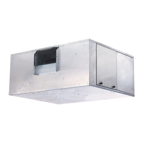
42BHC UNIT WITH ELECTRIC HEAT
Copyright 2003 Carrier Corporation
Product
Data
STANDARD 42BHC UNIT
42BHC
System Fan Coil
800 to 4000 Cfm
Satisfy All Your Design Requirements
with Carrier's Versatile 42BHC Fan
Coil Unit
• A selection of 6 sizes covers
capacities from 800 to 4000 cfm
• Choice of motors, from
eliminates oversizing
• Wide range of coil options for 2-pipe
or 4-pipe system
• Optional DX coils with expansion
valve and distributor
• Single and three-phase electric
heat (1.0 to 40 kW)
Features/Benefits
The 42BHC fan coil unit
provides year-round comfort
air conditioning with central
station operating economy.
A variety of coil options
reduces first cost
Four, 6 or 8-row cooling coils combine
the capacities you need with the most
efficient heat transfer surface. For
4-pipe systems, select either of two
split-coil options. Coils consist of alu-
minum fins securely bonded to
OD seamless copper tubes. Each fin's
aluminum collar ensures accurate con-
trol of the fin spacing, while complete-
ly covering the tubes to lengthen coil
life. All coils also feature manual air
vents, with automatic air vent available
as an option.
Fan wheels are designed to
provide low operating costs
The forward-curved, centrifugal,
double-inlet fans are statically and
dynamically balanced at the factory to
minimize transmission of vibration
to the building structure.
Form 42BHC-1PD
1
/
to 3 hp,
4
1
/
-in.
2
Advertisement
Table of Contents

Related Manuals for Carrier 42BHC


Summary of Contents for Carrier 42BHC
-
Page 1: Features/Benefits
42BHC System Fan Coil Data 800 to 4000 Cfm Satisfy All Your Design Requirements with Carrier’s Versatile 42BHC Fan Coil Unit • A selection of 6 sizes covers capacities from 800 to 4000 cfm • Choice of motors, from to 3 hp, eliminates oversizing •... -
Page 2: Table Of Contents
Q – 6/2, Same End Conn. easy-to-maintain units R – 8, 2-Pipe 1 – 4 With Electric Heat Size The 42BHC casings are fabricated 2 – 6 With Electric Heat Nominal from heavy-gage galvanized G90 steel, 3 – 8 With Electric Heat –––––––––––... -
Page 3: Factory-Installed Options
Factory-installed options The 42BHC units are designed to offer maximum flexibility Electric heat is available with the following staging options in application, accessibility for service, quiet operation and (3-phase staging is balanced). durability. • 1 to 4 kW 1 stage only — single phase Motors —... -
Page 4: Dimensions
Dimensions 42BHC BASE UNIT WITH 4 x 4 J BOX HANGER ROD (TYP. OF 4) 1" INSET FROM A & B DIM. UNIT INSTALLATION REF. VIEW ONLY 4X4 J-BOX (SAME SIDE AS HANGER ROD SIDE ACCESS PANEL COIL CONNECTIONS) TOP VIEW HOLES 5/8"... - Page 5 42BHC WITH MOTOR CONTROL OPTION HANGER ROD (TYP. OF 4) 1" INSET FROM A & B DIM. UNIT INSTALLATION REF. VIEW ONLY CONTROL BOX (SAME SIDE AS COIL CONNECTIONS) HANGER ROD HOLES 5/8" TOP VIEW (TYP. OF 4) SIDE ACCESS PANEL 1"...
- Page 6 Dimensions (cont) 42BHC WITH ELECTRIC HEAT HANGER ROD (TYP. OF 4) 1" INSET FROM A & B DIM. UNIT INSTALLATION REF. VEW ONLY HANGER ROD CONTROL BOX HOLES 5/8" (SAME SIDE AS (TYP. OF 4) SIDE ACCESS PANEL COIL CONNECTIONS) TOP VIEW COIL SUPPLY CONN.
- Page 7 UNIT CORNER WEIGHTS (lb) RIGHT HAND UNIT LEFT HAND UNIT RIGHT-HAND UNITS LEFT-HAND UNITS UNIT TOTAL CONFIGURATION 42BHC WEIGHT No Heat With Heat No Heat With Heat No Heat With Heat No Heat With Heat No Heat With Heat No Heat With Heat NOTE: Unit weights (shown in pounds) ±10 percent, are based on the largest water-filled coil and 1 Hp motor.
-
Page 8: Selection Procedure
Selection procedure This section provides capacity tables for the 42BHC unit. SC = SCb x Cs x Es Capacity tables are based on nominal cfm. Correction = 34.9 x .96 x 1.00 factors are provided for other operating conditions as = 33.50 MBtuh... -
Page 9: Performance Data
0.30 0.43 0.38 9000 0.90 0.73 0.25 0.38 0.33 NOTE: Use Sensible Heat correction factors when calculating heating capacity. 42BHC HOT WATER CAPACITY CORRECTION FACTORS ENTERING WATER TEMPERATURE (F) ENTERING AIR TEMPERATURE (F) 0.455 0.545 0.636 0.727 0.818 0.909 1.000 1.091... - Page 10 Performance data (cont) 42BHC NOMINAL COOLING CAPACITIES COOLING* UNIT SIZE NOMINAL CFM COIL ROWS 42BHC Total Capacity (MBtuh) Sensible Capacity (MBtuh) 29.9 20.9 23.2 18.1 17.7 15.5 40.7 26.2 32.2 22.6 24.4 19.3 46.8 29.3 38.0 25.3 29.1 21.5 47.8 32.5...
- Page 11 42BHC 4-ROW COOLING CAPACITY (by Gpm) 75 F DB/ 63 F WB 80 F DB/67 F WB 85 F DB/71 F WB UNIT 40 F EWT 45 F EWT 50 F EWT 40 F EWT 45 F EWT 50 F EWT...
- Page 12 Performance data (cont) 42BHC 8-ROW COOLING CAPACITY (by Gpm) 75 F DB / 63 F WB 80 F DB / 67 F WB 85 F DB / 71 F WB UNIT 40 F EWT 45 F EWT 50 F EWT...
- Page 13 Wet Bulb Temperature — ∆ ∆ ∆ ∆ T Change in Water Temperature (F) — 42BHC 8-ROW COOLING CAPACITY (by ∆ ∆ ∆ ∆ T) 75 F DB/63 F WB 80 F DB/67 F WB 85 F DB/71 F WB UNIT ∆...
- Page 14 DIRECT EXPANSION (DX) BASE COOLING CAPACITIES* (MBtuh) 4-ROW COIL ENTERING-AIR TEMPERATURE (F) — DB/WB CONNECTION UNIT R-22 SIZE (in.) SIZE SUCTION 75/63 80/63 75/67 80/67 80/71 85/71 42BHC TEMP (F) Liquid Suction 17.1 13.0 17.8 16.1 21.8 12.0 22.1 15.0 27.0 13.8 27.2 16.9...
- Page 15 DIRECT EXPANSION (DX) BASE COOLING CAPACITIES* (MBtuh) (cont) 6-ROW COIL ENTERING AIR TEMPERATURE (F) — DB/WB CONNECTION UNIT R-22 SIZE (in.) SIZE SUCTION 75/63 80/63 75/67 80/67 80/71 85/71 42BHC TEMP (F) Liquid Suction 21.3 15.4 21.8 18.8 26.6 14.3 26.8 17.6 32.3 16.3 32.4 19.6 16.3...
- Page 16 Performance data (cont) UNIT HORSEPOWER DATA TABLE TOTAL STATIC PRESSURE (in. wg) UNIT SIZE BLOWER 42BHC 0.07 0.09 0.11 0.12 0.14 1000 0.16 1055 0.18 1108 0.20 1159 0.22 0.10 0.11 0.13 0.15 0.17 1018 0.19 1071 0.21 1123 0.24 1172 0.26...
- Page 17 42BHC COMPONENT STATIC RESISTANCE (in. wg) WET COIL DRY COIL ONE-INCH ONE-INCH TWO-INCH TWO-INCH UNIT NOMINAL CABINET THROWAWAY PLEATED THROWAWAY PLEATED SIZE FILTER FILTER FILTER FILTER 0.04 0.18 0.27 0.36 0.02 0.04 0.08 0.13 0.17 0.02 0.08 0.04 0.06 0.06 0.25...
-
Page 18: Performance Data
Performance data (cont) 42BHC WATER PRESSURE DROP (ft. wg) FOR CV FACTOR AND WATER FLOW RATE (GPM) WATER FLOW RATE (GPM) FACTORS 0.5 1.0 1.5 2.0 9.5 10.0 10.5 110 11.5 12.0 13.0 14.0 15.0 16.0 17.0 18.0 19.0 20.0 0.9 3.6 8.1 14.4 22.5 32.4... -
Page 19: Typical Wiring Schematics
Typical wiring schematics BASE UNIT, SINGLE-PHASE POWER MOTOR CONTROL/DISCONNECT OPTION SINGLE-PHASE POWER... -
Page 20: Typical Wiring Schematics
Typical wiring schematics (cont) BASE UNIT, THREE-PHASE POWER MOTOR CONTROL/DISCONNECT OPTION THREE-PHASE POWER... -
Page 21: Electrical Data
Electrical data 42BHC ELECTRIC HEATER DATA AVAILABILITY 42BHC ELECTRIC HEATER DATA 42BHC UNIT SIZE FULL LOAD AMPS Single-Phase Three-Phase — — — — — 120 V 208 V 240 V 277 V 208 V 240 V 480 V — —... -
Page 22: Guide Specifications
Unit shall be complete with water coils, fan(s), G. Electric Heat: motor, belt drive, drain pan, and filter. Electric heaters are available on the 42BHC units. B. Casing: The heater shall be constructed of high-grade resis- Construction shall be heavy-gage galvanized steel, tance wire supported by ceramic insulators on plated lined with one-in. - Page 23 d. Unit shall be equipped with either a 4-row b. Unit shall be equipped with edge-sealed, DX (direct expansion) cooling coil or a 1-in. thick foil-faced insulation. 6-row DX cooling coil as required. * 4. Controls: e. For installation in a 4-pipe system the unit a.
- Page 24 Carrier Corporation • Syracuse, New York 13221 10-03 Manufacturer reserves the right to discontinue, or change at any time, specifications or designs without notice and without incurring obligations. Book 3 Book 4 Pg 24 Catalog No. 524-232 Printed in U.S.A.
Need help?
Do you have a question about the 42BHC and is the answer not in the manual?
Questions and answers