Table of Contents
Advertisement
Quick Links
Power Capacitors
MN230001EN
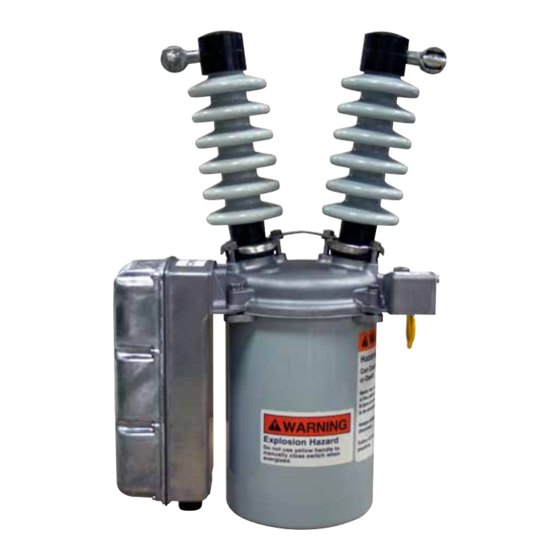
Type NR oil switch maintenance instructions
NR Switch Family Manufactured in Greenwood, SC
NR CP541000001 through CP541999999
NRV CP542000001 through CP542999999
Notice: This document is also applicable to product serial numbers beginning with the characters CP57.
Effective February 2016
Supersedes S230-60-8 October 2013
COOPER POWER
SERIES
Advertisement
Table of Contents

Related Manuals for Eaton Cooper Power NR Series


Summary of Contents for Eaton Cooper Power NR Series
- Page 1 COOPER POWER Power Capacitors SERIES Effective February 2016 MN230001EN Supersedes S230-60-8 October 2013 Type NR oil switch maintenance instructions NR Switch Family Manufactured in Greenwood, SC NR CP541000001 through CP541999999 NRV CP542000001 through CP542999999 Notice: This document is also applicable to product serial numbers beginning with the characters CP57.
- Page 2 CONTENTS OF THIS DOCUMENT SHALL NOT BECOME PART OF OR MODIFY ANY CONTRACT BETWEEN THE PARTIES. In no event will Eaton be responsible to the purchaser or user in contract, in tort (including negligence), strict liability or other- wise for any special, indirect, incidental or consequential damage or loss whatsoever, including but not limited to damage or...
-
Page 3: Table Of Contents
Contents SAFETY INFORMATION Safety Information ................iv PRODUCT INFORMATION Introduction . -
Page 4: Safety Information
FOR LIFE FOR LIFE Eaton meets or exceeds all applicable industry standards relating to product safety in its Cooper Power™ series products. We actively promote safe practices in the use and maintenance of our products through our service literature, instructional training programs, and the continuous efforts of all Eaton employees involved in product design, manufacture, marketing, and service. -
Page 5: Product Information
Introduction dry storage area. Service Information MN230001EN covers the maintenance instructions for Eaton's Cooper Power™ series Type NR electrically-operated, single-phase, oil switches. This Standards includes their general description, operating principles and Type NR oil switches are designed and tested in accordance instructions for periodic inspection and shop repairs. -
Page 6: Ratings And Specifications
Ratings and specifications Table 1. Electrical Data (Control) Description Rating Nominal operating voltage (Vac) (50/60 Hz only) Operating voltage range (Vac) 95 – 130 190 – 260 Closing-motor current (amp) Switch response time, opening (sec) Switch response time, closing (sec) Table 2. -
Page 7: Maintenance
Casting levels. In the absence of specific operating experience, Eaton recommends the switch be inspected and serviced every 1200 operations or three years, whichever comes first. In no case should the service interval, between... -
Page 8: Operating Instructions
13. Install new tank wall liners and fill the tank with clean, CAUTION new insulating oil to within one inch of the top of the tank flange. Oil capacity is approximately 1.5 gallons. Dielectric failure, equipment damage. Never use volatile solutions, detergents, or water-soluble cleaners when ote: Use only new, or like-new reconditioned transformer... -
Page 9: Manual Operation
Manual operation Test 1: Proceed as follows: The switch may be manually opened and closed by operat- Close the switch. ing the yellow handle under the sleet hood. Ground switch tank and head. Manual operation does not affect the status of the ote: Apply proper test voltage to one of the bushing electrically operated actuator. -
Page 10: Shop Repair Procedures
Shop repair procedures Aluminum Clamping The operations described in this section should be Ring performed under the cleanest conditions possible. The repair work, except for bushing replacement, will be simplified if the work bench is arranged so the mechanism/ head assembly can be inverted (bushings down). No special tools are required for any of the repair procedures. -
Page 11: Moving Contacts
Contact resistance* Standard: 750-875 mΩ Contact Retaining Screws Extra Creepage (17 inch): 875-1000 mΩ 20 kV (125 kV BIL): 845-945 mΩ Moving contacts Minor pitting can be smoothed with crocus cloth. If contacts show appreciable wear due to arc erosion, replace as Moving Contact follows: Remove the round head screws and lockwashers that... -
Page 12: Moving Contact Arm Assembly
Moving contact arm assembly Reassemble the new contact arm assembly, which includes the moving contact bar, to the contact box. To replace the moving contact arm assembly proceed as follows: Detach both opening springs from toggle link (Figure 8). Pull back latch lever assembly and remove C-ring which secures the toggle link to the bell crank lever. -
Page 13: Complete Contact Box Assembly
With the mechanism closed, the moving contacts Operating Shaft Drive Lever should be within 1/16-inch of full engagement, as measured between the top edge of the moving contact insulator and the bottom edge of the contact box side plate as shown in Figure 10. To obtain this dimension, Elastic Stop Nut adjust the effective length of the insulated operating link by adjusting the attaching point for the contact... -
Page 14: Selector And Holding Switches
Selector and holding switches To replace the selector switch, or holding switch if so equipped, proceed as follows: Heat the solder joint at the common terminal of the selector switch to disconnect black lead (Figure 12). Use a gun rated no higher than 100 watts and use only 50-50 or 40-60 rosin core solder for repair work. -
Page 15: Actuator Assembly Replacement
Actuator assembly replacement Head mechanism The head mechanism requires no periodic maintenance. To replace the actuator assembly proceed as follows: Observe the following procedure when disassembling the Pull yellow handle down to open switch contacts. head mechanism: Remove elastic stop nut, lockwasher and flatwasher Remove the contact structure as described in "Shop from operating shaft. - Page 16 To replace the latch lever assembly: Remove screws that secure the shaft retainers to the head casting. Lift out the latch lever assembly. When reassembling, slip the latch lever torsion spring and latch lever onto the latch lever shaft. D. Screw the two shaft retainers to the head casting to secure the latch lever shaft.
- Page 17 This page intentionally left blank. TYPE NR OIL SWITCH MAINTENANCE INSTRUCTIONS MN230001EN February 2016...
-
Page 18: Type Nr/Nrv Service Parts Diagram
Service parts list Figure 18. Type NR oil switch service parts. TYPE NR OIL SWITCH MAINTENANCE INSTRUCTIONS MN230001EN February 2016... -
Page 19: Type Nr/Nrv Service Parts List
To assure correct receipt of any part order, always include only those parts and assemblies usually furnished for repair switch type and serial number. Because of Eaton's or involved in the maintenance procedures described in continuous improvement policy, there may be instances this manual. -
Page 20: Actuator And Housing Service Parts Diagram
Figure 19. Actuator and housing service parts. TYPE NR OIL SWITCH MAINTENANCE INSTRUCTIONS MN230001EN February 2016... -
Page 21: Actuator And Housing Service Parts List
Actuator and housing service parts Item Description Catalog Number Machine screws, Fil hd. #10-24 x 7/8 sst 999904250369A Cover GR00323 Gasket GR00121 KA20200003 Split lockwasher, med, 1/4 bronze 900830025000A Plain washer, #14S, brass 900525026056A Switch Assembly Limit Switch KA23980002 Holding KA23980001 Auxiliary (SPDT) GRA0364... - Page 22 This page intentionally left blank. TYPE NR OIL SWITCH MAINTENANCE INSTRUCTIONS MN230001EN February 2016...
- Page 23 This page intentionally left blank. TYPE NR OIL SWITCH MAINTENANCE INSTRUCTIONS MN230001EN February 2016...
- Page 24 2300 Badger Drive Waukesha, WI 53188 United States Eaton.com/cooperpowerseries © 2016 Eaton Eaton is a registered trademark. For Eaton's Cooper Power series product All Rights Reserved information call 1-877-277-4636 or visit: Printed in USA All trademarks are property Publication No. MN230001EN of their respective owners.
Need help?
Do you have a question about the Cooper Power NR Series and is the answer not in the manual?
Questions and answers