
Related Manuals for Eaton VFI


Summary of Contents for Eaton VFI
- Page 1 COOPER POWER Underground Distribution Switchgear SERIES Effective March 2018 MN285006EN Supersedes December 2015 Type VFI, Fluid-insulated Switchgear; Installation, Operation and Maintenance Instructions...
-
Page 2: Disclaimer Of Warranties And Limitation Of Liability
CONTENTS OF THIS DOCUMENT SHALL NOT BECOME PART OF OR MODIFY ANY CONTRACT BETWEEN THE PARTIES. In no event will Eaton be responsible to the purchaser or user in contract, in tort (including negligence), strict liability or other-wise for any special, indirect, incidental or consequential damage or loss whatsoever, including but not limited to... -
Page 3: Table Of Contents
VFI switchgear operation ........ -
Page 4: Safety Instructions
FOR LIFE FOR LIFE Eaton meets or exceeds all applicable industry standards relating to product safety in its Cooper Power™ series products. We actively promote safe practices in the use and maintenance of our products through our service literature, instructional training programs, and the continuous efforts of all Eaton employees involved in product design, manufacture, marketing, and service. -
Page 5: Product Information
T374 .0 satisfy a problem not covered sufficiently for the user’s purpose, please contact your Eaton representative. VFI switchgear can also be specified with a variety of control options to meet specific distribution system protection requirements Acceptance and initial inspection... -
Page 6: Electronic Control
● Interrupter Loadbreak switch In many configurations the Type RVAC switch is integrated within the VFI switchgear. Refer to the Operation section of MN285005EN Type RVAC Fluid-Insulated Vacuum Switchgear; Installation, Operation, and Maintenance Figure 1 . Vacuum fault interupter assembly Instructions for operation information for the RVAC switch. -
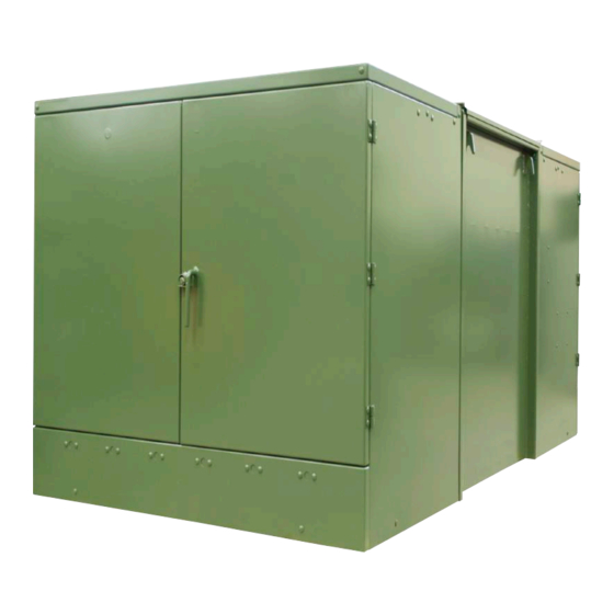
Page 7: Cabinet Construction
IEEE Std G123 .1 C37 .74™-2003 standard. Finish VFI switchgear is finished in a green color which conforms to Munsell 7GY 3.29/1.5 Green. The coating conforms to INSTALLATION, OPERATION AND MAINTENANCE INSTRUCTIONS MN285006EN March 2018... -
Page 8: Weight
The Type VFI switchgear is equipped with hotstick-operable handles that may be located on the tap- and/or source-side of the unit. The VFI switchgear can be configured for either single-phase or ganged three-phase operation (all three phases operated simultaneously with a single handle). -
Page 9: Operation
Type VFI, Fluid-insulated Switchgear NOTICE A. Prior to making connections, make sure that the source-side and tap-side cable elbows are correctly The use of Envirotemp™ FR3™ dielectric fluid is identified and that the switchgear unit is oriented limited to a minimum operating temperature of 0 °C correctly for the installation. -
Page 10: Application
. G108 .0 personal injury . G105 .1 The Type VFI switchgear is a deadfront design. All live parts Opening interrupter are contained within the sealed tank enclosure. A routine maintenance inspection program is required to ensure The vacuum fault interrupter is opened by pulling the proper operation. -
Page 11: Internal Inspection And Repair
Verify manual operation of each the 68 °F (20 °C) fluid fill level with clean, dry insulating switch and VFI. Contact the manufacturer with any fluid. concerns. -
Page 12: Frequency Of Maintenance
Type VFI, Fluid-insulated Switchgear To assure trouble-free operation of this equipment, a Where local governing authorities allow access to regular schedule of fluid testing and fluid maintenance is energized equipment, the following precautions must required. A routine fluid testing and maintenance schedule... -
Page 13: Fuid Fill Guidelines
15. Retighten sampling valve to “finger tight” plus a 1/4 indicate a problem with either the fluid or the unit. Contact turn. Reinstall cap, and leave it “finger tight” . your Eaton representative for technical assistance. INSTALLATION, OPERATION AND MAINTENANCE INSTRUCTIONS MN285006EN March 2018... -
Page 14: Replacement Parts
Water Content (ppm) Service Recommendation < 25 Continue with Eaton recommended maintenance schedule (inspection and sampling every 2 years). Obtain another fluid sample for moisture analysis in 6 months to determine if moisture levels are rising. Refer 25 – 35 to the Fluid sampling guidelines section in this manual. -
Page 15: Testing
25.5 kV AC RMS or 39.75 kV DC 30 kV AC RMS or 58.5 kV DC Figure 5 . VFI Tester Unit - Catalog Number KVFI TESTER 37.50 kV AC RMS or 77.25 kV DC * 75% of the production AC withstand test voltage, per IEEE Std C37 .60... - Page 16 Eaton.com/cooperpowerseries © 2018 Eaton All Rights Reserved Printed in USA Eaton is a registered trademark. Publication No. MN285006EN For Eaton‘s Cooper Power series product March 2018 information, call 1-877-277-4636 or visit: All trademarks are property www.eaton.com/cooperpowerseries. KA20480375 Rev: 09 of their respective owners.
Need help?
Do you have a question about the VFI and is the answer not in the manual?
Questions and answers