Table of Contents
Advertisement
This .pdf document is bookmarked
Operating Instructions and Parts Manual
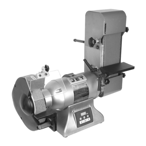
8-inch Grinder with Belt Sander
Models IBGB-248/248VS/436/436VS
Variable speed model IBGB-436VS shown
JET
427 New Sanford Road
LaVergne, Tennessee 37086
Part No. M-577248
Ph.: 800-274-6848
Edition 3 07/2019
www.jettools.com
Copyright © 2019 JET
1
Advertisement
Table of Contents


Need help?
Do you have a question about the IBGB-248VS and is the answer not in the manual?
Questions and answers