Table of Contents
Advertisement
Quick Links
Advertisement
Table of Contents

Related Manuals for Minuteman SCV 28


Summary of Contents for Minuteman SCV 28
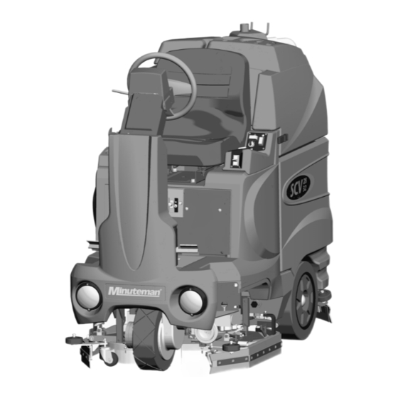
- Page 1 SCV 28/32 RIDER SCRUBBER ■ ■ ■ OPERATION SERVICE PARTS CARE...
- Page 2 This manual is furnished with each new MINUTEMAN SCV 28/32 This provides the necessary operating and preventive maintenance instructions. Operators must read and understand this manual before operating or servicing this machine. This machine was designed to give you excellent performance and efficiency. For best results and minimal cost, please follow the general guidelines below: •...
-
Page 4: Table Of Contents
Main Keyboard.........3 GENERAL MACHINE Horn button ..........3 TROUBLESHOOTING ......21 Directional switch ........3 MAIN KEYBOARD ........4 SCV 28/32 FAULT / DIAGNOSTIC CODES . 23 FULL FUNCTION MODE......4 DOUBLE SCRUB MODE......4 EXPLODED VIEWS........25 VACUUM ONLY MODE......4 MAIN ASSEMBLY I ........25 TRANSPORT MODE .......4... - Page 5 REAR SQUEEGEE ASSEMBLY 28” ..50 REAR SQUEEGEE ASSEMBLY 32” ..52 28” CYLINDRICAL SCRUB DECK ASSEMBLY ..........54 28” DISC SCRUB DECK ASSEMBLY ..56 32” CYLINDRICAL SCRUB DECK ASSEMBLY ..........58 32” DISC SCRUB DECK ASSEMBLY ..60 CYLINDRICAL DECK AND SIDE SQUEEGEE MOUNTING ......62 DISC SCRUBDECK AND SIDE SQUEEGEE MOUNTING..........64 28”...
- Page 6 Operators must read and understand this manual before operating or maintaining this machine. Do not operate this machine in flammable or explosive areas. This machine is designed solely for scrubbing dirt and dust in an indoor environment. Minuteman does not recommend using this machine in any other capacity.
-
Page 7: Important Safety Instructions
This machine is battery operated and designed to operate on 36 volts DC (6) 6-volt batteries. BATTERIES The recommended batteries are rated 370Ah (Minuteman P/N 956715). We do not recommend mixing AMP hour capacities. Any alternate battery sets can be used if they equal physical size and capacity. -
Page 8: Machine Components
MACHINE COMPONENTS REAR Rear squeegee Rear wheel Side squeegee Accelerator pedal Solution tank Steering column pivot Tilt-wheel lever LCD display panel Steering wheel Recovery tank lid Vacuum filter access Vacuum diverter Off-aisle wand Recovery tank Battery compartment Clean-out cap Recovery dump hose Safety latch Recovery hose Scrub deck... -
Page 9: Control Console
CONTROL CONSOLE For operator ergonomics, the control console houses all the primary function buttons are grouped in a central area. The key switch, headlight switch, and off-aisle wand switch are clustered in the back area. The directional switch (forward and reverse) is located in front of the console for easy fingertip operation. The horn button, function buttons, and indicators are located in the main central part of the console. -
Page 10: Main Keyboard
MAIN KEYBOARD FULL FUNCTION MODE When this mode is chosen, a green indicator light will illuminate within the full function icon. When the machine is running in this mode, all machine functions will be on. When the operator sets the directional switch to the forward position and steps the accelerator pedal, the solution pump will turn on, the brushes will turn on and be lowered to the floor, and the rear and side squeegees will be lowered to the floor as the vacuum motor turns on. -
Page 11: Water Flow Adjustment
KEY SWITCH INFORMATION BUTTON When switch is turned on, the Minuteman logo Pressing the “i” button will display hours logged on will appear in the middle of the screen. -
Page 12: Full Function Mode
FULL FUNCTION MODE DOUBLE SCRUB MODE The vacuum icon with moving arrows, the brush The brush pressure bars and water flow bars will pressure bars and water flow bars will be be displayed. displayed. VACUUM ONLY MODE TRANSPORT MODE The vacuum symbol will be displayed and no Silhouette of the machine will be displayed and bars displayed for brush and flow icons. -
Page 13: Low Battery Indicator
LOW BATTERY INDICATOR The battery gauge bar icon will be flashing to signal the operator that the machine is almost out of power. Once this signal is displayed to the operator, all functions will shut off including the transport mode. The operator has to turn the key switch OFF and then, ON to reset the machine. -
Page 14: Operation Of Controls
OPERATION OF CONTROLS POWER SAVE MODE The SCV is equipped with a power save feature to conserve battery power. If the key switch power is left ON and none of the controls are activated for a period of fifteen minutes, the SCV automatically goes into “power down mode”... -
Page 15: Mechanical & Parking Brake
MECHANICAL & PARKING BRAKE Located on the left side of the operator compartment on the floor is the mechanical brake which doubles as the parking brake. Even though the machine is equipped with a regenerative braking system, the mechanical brakes can be activated by pushing down on the pedal and apply brakes on the rear wheels. The mechanical brake also doubles as a Parking brake. -
Page 16: Battery Compartment
(make sure recovery tank has been drained before tilting). The battery compartment contains six 6-volt batteries connected in series. Connect the batteries according to the battery connection diagram (see diagram). The recommended batteries are 370Ah (Minuteman P/N 956715). -
Page 17: Scrub Deck
SCRUB DECK Minuteman offers two deck types (Cylindrical and Disc) to fit your specific needs. The SCV design is very dynamic wherein the decks are interchangeable in a matter of minutes whenever necessary (removal of four bolts, and two quick-connects). The cylindrical brush deck has five built-in spray jets to uniformly dispense cleaning solution on the floor and a wet sweeping debris tray to collect loose objects on the floor. -
Page 18: Scrub Deck Installation
SCRUB DECK INSTALLATION When installing a cylindrical deck to a machine: 1. Install brushes after the deck has been mounted to avoid flat spots on the brushes. 2. Use a piece of cardboard underneath the deck to prevent scratches to the painted surface when sliding the deck under the machine. - Page 19 SIDE SQUEEGEE The side squeegees (left and right) are attached to the machine mainframe. These items channel the dirty solution to the rear squeegee, helping contain the water within the machine’s cleaning path. These squeegees are raised when the scrub deck is in the raised position. When the scrub deck is deployed, the side squeegees are also lowered.
-
Page 20: Rear Squeegee
REAR SQUEEGEE The rear squeegee is the main element that acts as the conduit that transfers the spent solution into the recovery tank. A daily maintenance check of this component is essential to have optimum machine performance. The rear squeegee assembly is equipped with a universal front blade that allows the operator the option to use a slotted and a non-slotted side for specific applications. -
Page 21: Rear Squeegee Adjustment
REAR SQUEEGEE ADJUSTMENT 1. Ensure that the scrubber is on a relatively flat surface. Turn on the key switch and select the Vacuum only mode. This lowers the squeegee to the floor and turns the vacuum motor on. 2. Move the scrubber one or two feet forward slowly while someone behind the machine checks the rear squeegee blade (item 1) for uniform deflection to the floor. -
Page 22: Off-Aisle Wand Tool
OFF-AISLE WAND TOOL The off-aisle wand tool as described in the previous page is composed of the following items: 1. The recovery hose is connected to the end of the wand on one end and to the diverter assembly (item F) on the other end. This hose has swivel cuffs on both ends that allow the operator a good range of motion and the solution hose to be inside the recovery hose. -
Page 23: The Scv Rider
LCD panel) using the tilt wheel lever. 2. Turn the Key switch ON (I). The LCD panel will light up and display the Minuteman logo for a few seconds and display the Battery Condition icon and the last functional setting when the machine was turned off. - Page 24 7. Stepping on the Accelerator Pedal turns on the Transport, Brushes, Water Flow, Vacuum and lowers the Rear Squeegee accordingly to the Mode selected. If the operator steps on the accelerator pedal before, or turns the key switch “ON” at the same time, the machine will not move as a safety precaution.
-
Page 25: After Use
AFTER USE: 1. When finished scrubbing, select the Transport mode, all functions will shut off (brush will turn off and the scrub deck will raise up, water flow will cease, the rear squeegee will raise up and the vacuum motor will turn off). Drive the machine to a service area for daily maintenance and review items that may need service. -
Page 26: Maintenance Schedule
Clean Hopper on Cylindrical System • Have Minuteman check the vacuum motor carbon motor brushes once a year or after 300 operating hours. The brush motor carbon brushes should be checked every 500 hours or once a year. NOTE: Refer to the Service Manual for more detail on maintenance and service repairs. -
Page 27: General Machine Troubleshooting
Worn brushes Rotate or replace brushes Poor scrubbing Wrong brush or cleaning chemical Consult Minuteman performance Debris caught on scrub brushes Remove debris Moving machine too fast Slow down Not using enough solution... - Page 28 Recovery tank full Empty recovery tank Excessive foaming in recovery tank. Empty recovery tank. Use less or change chemical. Vacuum motor does not turn on Use defoaming agent. Fault code on LCD screen 7700 Check for motor overload. (Vacuum motor) Reset machine: Turn key switch off and restart.
-
Page 29: Scv 28/32 Fault / Diagnostic Codes
SCV 28/32 FAULT / DIAGNOSTIC CODES Code Technical Probable Cause Service Action Description Check for wiring short circuits on the 20- 0705 2.5V reference way connector on the SCV, the 16-way error All 070x codes – Wiring short connector on the LCD (if used) and the circuit between potentiometer wiring to the front panel switches &... - Page 30 7802 Traction motor Traction motor current has Excessive driving up an incline, or machine in foldback state exceeded current limit for the driven up against an obstacle or step. foldback time. Check for wiring short circuits on the 20-way connector on the SCV, the 16-way connector 7900 Emergency stop E-stop input active or wiring fault.
-
Page 35: Mainframe Assembly I
MAINFRAME ASSEMBLY I... -
Page 38: Front Drive Assembly
FRONT DRIVE ASSEMBLY... -
Page 40: Steering Assembly
STEERING ASSEMBLY... -
Page 42: Lcd Housing Assembly
LCD HOUSING ASSEMBLY... -
Page 43: Solution Tank Assembly
SOLUTION TANK ASSEMBLY... -
Page 45: Electrical Panel Assembly
ELECTRICAL PANEL ASSEMBLY... -
Page 46: Console Assembly
CONSOLE ASSEMBLY... -
Page 47: Recovery Tank Assembly I
RECOVERY TANK ASSEMBLY I... -
Page 49: Recovery Tank Ii
RECOVERY TANK II... -
Page 50: Diverter Assembly
DIVERTER ASSEMBLY... -
Page 51: Battery Box Assembly
BATTERY BOX ASSEMBLY... -
Page 52: Pump Assembly
PUMP ASSEMBLY... -
Page 55: Squeegee Mechanism Assembly
SQUEEGEE MECHANISM ASSEMBLY... -
Page 62: 28" Disc Scrub Deck Assembly
28” DISC SCRUB DECK ASSEMBLY... -
Page 68: Cylindrical Deck And Side Squeegee Mounting
CYLINDRICAL DECK AND SIDE SQUEEGEE MOUNTING... -
Page 70: Disc Scrubdeck And Side Squeegee Mounting
DISC SCRUBDECK AND SIDE SQUEEGEE MOUNTING... -
Page 72: 28" Side Squeegee (Right Side)
28” SIDE SQUEEGEE (RIGHT SIDE) -
Page 73: 28" Side Squeegee (Left Side)
28” SIDE SQUEEGEE (LEFT SIDE) -
Page 74: 32" Side Squeegee (Right Side)
32” SIDE SQUEEGEE (RIGHT SIDE) -
Page 75: 32" Side Squeegee (Left Side)
32” SIDE SQUEEGEE (LEFT SIDE) -
Page 78: Plumbing Diagram
PLUMBING DIAGRAM... -
Page 79: Wiring Diagrams
WIRING DIAGRAMS POWER WIRING... -
Page 80: Inputs To Controller
INPUTS TO CONTROLLER... -
Page 81: Outputs From Controller
OUTPUTS FROM CONTROLLER... -
Page 82: Keyboard Wiring
KEYBOARD WIRING... - Page 84 1/03...
Need help?
Do you have a question about the SCV 28 and is the answer not in the manual?
Questions and answers