Minuteman PORT A SCRUB 14 Instruction Manual
Floor scrubber drier
Hide thumbs
Also See for PORT A SCRUB 14:
- Instruction manual (35 pages) ,
- Instruction manual and spare parts list (48 pages)
Table of Contents
Advertisement
Advertisement
Table of Contents

Related Manuals for Minuteman PORT A SCRUB 14


Summary of Contents for Minuteman PORT A SCRUB 14
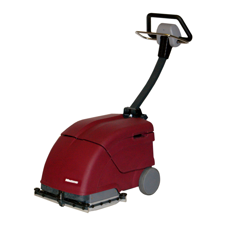
- Page 1 PORT A SCRUB 14 Floor Scrubber Drier...
-
Page 2: Table Of Contents
Contents Instruction Manual Preface....................... Introduction Proper Use......................Notes on Warranty....................Acceptance of the Machine................. General Safety Provisions Operation......................Transport......................Park Position....................... Handling Mains Cable..................Operation Machine......................Useful Advice for Optimum Cleaning..............Working Principle....................First Operation Assembly......................Before Operation....................Description Controls......................Control Panel...................... - Page 3 Spare Parts Manual Chassis Group..................... Handle Group...................... Brush Drive Group....................Brush Head Group....................Vacuum Motor Assembly..................Vacuum Motor Group..................Squeegee Group....................Squeegee Lifting System..................Water Feed System..................... Tank Group......................Drive Group......................Electrical Group....................Port A Scrub 14 Assy..................
-
Page 4: Instruction Manual
The Port A scrub 14 may be used , serviced and repaired by persons only that are familiar with the machine and are aware of possible hazards involved. The appropriate Accident Prevention Regulations as well as applicable general regulations about safety and health at work will have to be complied with. -
Page 5: Notes On Warranty
The terms of the sales contract apply. Damages are not subject to warranty if they are due to non-compliance with the maintenance and service provisions. Any maintenance work has to be performed by an authorized Minuteman service workshop and confirmed in the “Maintenance certificate “which is the warranty document. -
Page 6: Transport
Transport The front roller of the Port A scrub 14 has been fitted for parking the machine only and precludes damages to the floor .It is thus recommended to lift up the brush head as represented before transporting the Port A Scrub 14. -
Page 7: Operation
Operation Working Principle Port A scrub 14 Wet cleaning of hard floorings requires equipment with squeegee and brushes suitable for the type of floor to be cleaned. The rotating brushes and the cleaning lye scrub the dirt and clean the floor thoroughly while the squeegee collects the lye immediately. -
Page 8: Description
Maintenance or repair actions at the electric components have to be executed with adequate tools only and by qualified personnel only. 2. After taking the Port A scrub 14 to its park position, set the operating handle into its working position by releasing the button at the side. -
Page 9: Control Panel
Pump Switch ˜ The Port A Scrub 14 allows mixing of cleaning lye and fresh water in the tank. The amount of detergent required for cleaning can be regulated by the pump switch. If the switch is set to the position “I” the cleaning lye is continuously supplied. -
Page 10: Squeegee Governor
Forward · The front or the rear squeegee of the Port A Scrub 14 is lowered and has contact with the floor. The operator may change squeegee position according to the direction of travel of the machine. ˜ If the port A Scrub 14 is in its working position and pushed forward, the rear squeegee has contact with the floor while the front squeegee is lifted. -
Page 11: Mount / Dismount Brushes
Dismount Brushes ˜ Use the support roller located at the handle side of the Port A Scrub 14 to set the machine into its park position. ˜ Loosen screw. When inserting the brushes for the next operation, make sure to change position of the brush such that one- sided brush wearing is precluded. -
Page 12: Squeegee
Squeegee The Port A scrub 14 has been equipped with a squeegee of 450 mm working width. The squeegees can be lifted- out alternately Check the squeegee for collected foreign particles and Mount Squeegee (Initial Fitting) ˜ Lift squeegee and hold it to the squeegee holders (3). -
Page 13: Fill Water
Turn switch “B” ON to start suction turbine running. Turn all switches OFF after operation and remove the brushes from the Port A Scrub 14. Mount the brushes in inverse order of dismounting before next operation. This measure extends service life of the brushes. -
Page 14: Soiled And Fresh Water Tanks
Soiled and fresh water tanks Fresh water tank The Port A Scrub 14 is equipped with a soiled and a fresh water tank (lye tank). The filling amounts to 10 litres. Do not fill beyond the maximum Filter mark and do not exceed a water temperature of 50°C Floater A suction hose delivers the soiled water into the soiled water tank. -
Page 15: Electric System
Electric System The electric system of the Port A Scrub 14 operates at a mains voltage of 110-120V / 60Hz. After opening the machine top, the brush motor and the suction turbine are well accessible. A T10A fuse (E) protects the suction turbine and has to be replaced by the same type if blown (T stands for slow-blow). - Page 16 Wheel Rear wheel, dia Tank capacities Fresh water tank Soiled water tank Throughput , max. l/min Brush head No. of brushes Qty. Brush dia Brush speed Brush contact pressure, max.up to kg (N ) 16-19 Vacuum suction Nominal vacuum pressure, min. mm Hg 60-80 Electrical equipment...
-
Page 17: Maintenance
Brushes Intended Use Brush, PA Smooth floor Brush, PP Medium Smooth Floor Brush,Silicon Carbide Hard Floor Maintenance Maintenance work Compliance with our recommendations concerning maintenance work will give you the certitude always having a machine at your disposal, which is ready to work and in good operating condition. It is better to take precautions than to repair damages - and less expensive! Please contact your local contract dealer;... - Page 18 Service hours Maintenance work Daily every every every Check connections, extension cable and plug for good condition, replace defective cable Empty and clean (rinse) soiled water tank Check sealing strips at the squeegee for condition. Check squeegee for collected foreign matters and clean if required Check the floater for function Check filter sieve of the fresh water tank and clean if required..
-
Page 19: Spare Parts Manual
Port A Scrub 14 Floor Scrubber Drier Spare Parts Manual... -
Page 21: Chassis Group
Chassis Group Ref. Part Description Size 3180004 Base Frame Assy 3130077 Seal - W heel 931756 W heel 3130071 Bush-W heel 3130038 W asher-Main W heel 829306 Hex. Soc. CSK. Head Screw SS M6x16 931128 Cover W heel 931045 Hex Soc. Head Pin 3130054 Bush LH&RH- Pillar Handle 931753... - Page 22 25 22 33 30 26...
-
Page 23: Handle Group
Handle Group Ref. Part Description Size 3180016 Handle (W eldm ent) 3180029 S teering As s y 931281 S w itc h C over - B ottom 3130120 S w itc h C over - T op 847001 C irc uit B reaker 9A 928107 Nut - C irc uit B reaker 925124... -
Page 25: Brush Drive Group
Brush Drive Group Ref. Part Description Size 3130002 Hous ing - Brus h 3180022 Hous ing As s y-Gear Support 931171 Hinge - Idler End 3180062 Idler Support As s y Brus h 831306 Hex. Soc .Hd C ap Sc rew -SS M6X16 3180053 Brus h Motor... -
Page 27: Brush Head Group
Brush Head Group Ref. Part Description Size 3130006 Housing-Gear Support 875010 Bearing 6003 2RS 3180008 Sprocket Assy Gear 931027 Drive Key 931815 Idler - Plain Assy 831307 Hex. Soc. Hd Cap Screw - St M6X20 875011 Bearing 608 2Z 931036 Gear-LH 931035 Gear-RH... -
Page 29: Vacuum Motor Assembly
Vacuum Motor Assembly Ref. Part Description Size 3130046 Hs g B ottom - V.M 931197 Gas ket - V.M 931857 V.M w ith C onnec tor As s y 3130047 Hs g Top - V.M 845052 W as her - S S 304 5.2X10X1.6 837210 S elf Tap S c rew... - Page 30 HOLDER-LOAT TANK-COLLECTION SQUEEGEE-REAR SQUEEGEE-FRONT...
-
Page 31: Vacuum Motor Group
Vacuum Motor Group Ref. Part Description Size 836206 C R P H S elf Tapping S c rew - S S 3.5X16 845039 W as her - S S 4.0X8.0X0.5 931132 Guide - Float 931810 Float 931196 Gas ket - Float 931850 Hos e As s y - Vac uum 931851... -
Page 33: Squeegee Group
Squeegee Group Ref. Part Description Size 3130051 B ody S qg 931170 Valve Top 931126 Valve B ottom 832213 Hex. S oc . Hd C ap S c rew - S S M5X50 931233 Lip - S qg. Inner 931224 Lip - S qg. - Page 34 12 19 18 15 14 13...
-
Page 35: Squeegee Lifting System
Squeegee Lifting System Ref. Part Description Size 931181 C lip - C lam p 931051 P in 6 - P illar S qg 3180013 S queegee Front 3180014 S queegee R ear 931804 C able As s y - S queegee 3180027 S qg R od As s y - Front 3180026... -
Page 37: Water Feed System
Water Feed System Ref. Part Description Size 931142 Holder - Noz z le 931198 W as her - Noz z le 931816 Noz z le As s y 931143 Nut - Noz z le 3130113 Vibrating Pad-Pum p 925325 Vibrating Pum p 3130111 C onnec tor-Pum p 928054... -
Page 39: Tank Group
Tank Group Ref. Part Description Size 3130117 Bottom Hous ing 931125 C ap - V.M 931144 Yoke Hinge - Lid (R ight) 836206 C R PH Self Sc rew -SS 3.5X16 931162 Yoke Hinge - Lid (Left) 3130068 Mounting Plate - Bot. Hs g 836004 C R PH Self Sc rew - SS 3.5X13... -
Page 41: Drive Group
Drive Group Ref. Part Description Size 3130040 S upport P late-Hous ing 844061 W as her 6.4X12X16 831307 Hex S oc Hd C ap S c rew M6X20 845041 W as her-S S 4.3X9X0.8 818105 C R P an Head-S S M4X15... -
Page 43: Electrical Group
Electrical Group Ref. Part Description Size 3130055 B as e - Term inal 931150 C over - Term inal 836006 C R P H S elf S c rew - S S 3X16 931195 Grom m et - Term inal 931844 C onnec tor - P illar 931123... - Page 44 -M2.X4...
- Page 45 Electrical Group Ref. Part Description Size 931874 7Core cable assy 931863 Wire Assy - (S2 to F2) 931864 Wire Assy - (S1 to F1) 931865 Wire Assy - (X3 to S1, S2 & S3 +VE) 931866 Wire Assy - (X3 to S1, S2 & S3 -VE) 931895 2 Core cable assy (Pump) 931868...
-
Page 47: Port A Scrub 14 Assy
Port A Scrub 14 Assy Ref. Part Description Size 925012 W as her-Bridge 829307 Hex Soc C SK Hd Sc rew -SS M6X20... -
Page 48: Limited Warranty
In addition, Minuteman International, Inc will, at its option, honor labor warranty claims for the first 6 months from date of sale, provided such claims are submitted through and approved by factory authorized repair stations.
Need help?
Do you have a question about the PORT A SCRUB 14 and is the answer not in the manual?
Questions and answers