Table of Contents
Advertisement
Quick Links
Advertisement
Table of Contents

Subscribe to Our Youtube Channel
Related Manuals for Minuteman SCV 28/32


Summary of Contents for Minuteman SCV 28/32
- Page 1 SCV 28/32 RIDER SCRUBBER ■ ■ ■ OPERATION SERVICE PARTS CARE...
- Page 2 This manual is furnished with each new MINUTEMAN SCV 28/32. This provides the necessary operating and preventive maintenance instructions. Operators must read and understand this manual before operating or servicing this machine. This machine was designed to give you excellent performance and efficiency. For best results and minimal cost, please follow the general guidelines below: •...
-
Page 4: Table Of Contents
TABLE OF CONTENTS IMPORTANT SAFETY INSTRUCTIONS ................ 7 FOR SAFETY DURING OPERATION: ................ 7 FOR SAFETY WHEN SERVICING or MAINTAINING MACHINE:....... 7 INSPECTION ........................8 ELECTRICAL ......................... 8 BATTERIES........................8 OPERATOR RESPONSIBILITY ..................8 MACHINE OVERVIEW, FRONT ..................9 MACHINE OVERVIEW, REAR ..................10 OPERATOR COMPARTMENT.................. - Page 5 INSTALLATION INSTRUCTIONS ................22 IMPORTANT NOTE WHEN INTERCHANGING SCRUB DECKS ......23 SIDE SQUEEGEES ...................... 24 DISK DECK SIDE SQUEEGEE COMPONENTS ............24 CYLINDRICAL DECK SIDE SQUEEGEE COMPONENTS ........25 BRUSH CHANGES ON THE CYLINDRICAL DECK............ 25 REAR SQUEEGEE ....................... 26 REAR SQUEEGEE COMPONENTS .................
- Page 6 28” DISK SCRUBDECK..................... 67 28” DISK SCRUBDECK BOM ................... 68 32” DISK SCRUBDECK..................... 69 32” DISK SCRUBDECK BOM ................... 70 CYLINDRICAL SCRUBDECK SIDE SQUEEGEE (LEFT SIDE)....... 71 CYLINDRICAL SCRUBDECK SIDE SQUEEGEE (RIGHT SIDE) ......72 DISK SCRUBDECK SIDE SQUEEGEE (LEFT SIDE) ..........73 DISK SCRUBDECK SIDE SQUEEGEE (RIGHT SIDE)..........
-
Page 7: Important Safety Instructions
Operators must read and understand this manual before operating or maintaining this machine. Do not operate this machine in flammable or explosive areas. This machine is designed solely for scrubbing dirt and dust in an indoor environment. Minuteman does not recommend using this machine in any other capacity. -
Page 8: Inspection
This machine is battery operated and designed to operate on 36 Volts DC (6) 6-volt batteries. BATTERIES The recommended batteries are rated 275Ah (Minuteman P.N. 956740). We do not recommend mixing Amp Hour capacities. Any alternate battery sets can be used if they are of equal physical size and capacity. See “Battery Compartment” for service and installation. -
Page 9: Machine Overview, Front
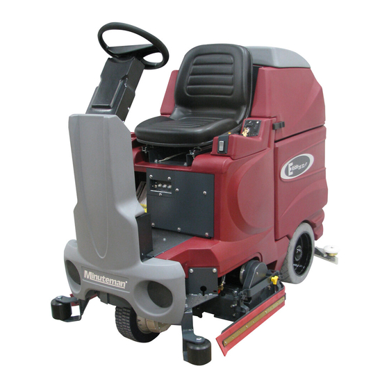
MACHINE OVERVIEW, FRONT Front Drive Wheel Directional Switch Side Squeegee Safety Latch Accelerator Pedal Battery Compartment Steering Tilt Lever Solution Tank Steering Wheel Electrical Panel Operator’s Seat Rear Squeegee Recovery Tank Lid Real Wheel Recovery Tank Scrubdeck Control Console Roller Bumper... -
Page 10: Machine Overview, Rear
MACHINE OVERVIEW, REAR Rear Squeegee Vacuum Filter Access Rear Wheel Vac Inlet Assembly Side Squeegee Recovery Tank Accelerator Pedal Battery Compartment Solution Tank Clean-Out Cap Steering Tilt Lever Recovery Drain Hose Steering Wheel Recovery Hose Recovery Tank Lid Scrubdeck... -
Page 11: Operator Compartment
OPERATOR COMPARTMENT Operator’s Seat Steering Wheel Solution Tank Lid Directional Switch Cup Holder Control Panel Solution Tank Safety Latch Accelerator Pedal... -
Page 12: Control Console
CONTROL CONSOLE For operator ergonomics, the control console houses all the primary function controls in a central area. The key switch and optional headlight and off-aisle wand switches are clustered in the back portion of the console. The directional switch (forward/reverse) is located at the front of the console for easy fingertip operation. -
Page 13: Operation Modes
OPERATION MODES 1. REGULAR SCRUB MODE When the machine is running in this mode, the machine will perform all operations. This mode can be used for day-to-day tasks under normal conditions. When the operator sets the directional switch to forward and activates the accelerator pedal, the solution pump will turn on, the brushes will turn on and be lowered to the floor,... -
Page 14: Vacuum Only Mode
After double scrubbing, the operator should use the vacuum only mode to recover the dirty solution water from the floor. 4. VACUUM ONLY MODE When the machine is running in this mode, the machine will only lower the rear squeegee and turn on the vacuum system to recover the dirty solution from the floor. This mode is usually chosen after double scrubbing to recover the dirty solution but it can also be used to pick up spills. -
Page 15: Fault / Diagnostic Codes
FAULT / DIAGNOSTIC CODES When an error or fault occurs within the machine, a fault code will appear on the battery gauge represented by a specific number of flashing LEDs. The figure below shows a listing of the different codes. FAULT / DIAGNOSTIC CODES DECAL... -
Page 16: Empty Solution Tank Indicator
EMPTY SOLUTION TANK INDICATOR Once the solution tank has become empty, the battery gauge will blink a solid 9 LEDs at a constant interval to alert the operator that the solution tank needs to be filled. LOW BATTERY INDICATOR If the battery life is low, the battery gauge bar icon will be flashing to inform the operator that the machine is almost out of power. -
Page 17: Operation Of Controls
OPERATION OF CONTROLS STEERING WHEEL The steering wheel is adjustable for operator comfort by pulling the tilt- steering lever up and positioning the steering wheel up or down (there are three possible positions). Pulling on the tilt-steering lever and positioning the steering column in an upright position provides the operator with more room when climbing up and down the... -
Page 18: Emergency Disconnect Button
The battery compartment contains six, 6- volt batteries connected in series. Connect the batteries according to the battery connection diagram (see diagram). The recommended batteries are 275Ah (Minuteman P.N. 956740). The two batteries positioned in the center are offset and held in position by two steel spacers. -
Page 19: Battery Connection Diagram
BATTERY CONNECTION DIAGRAM BATTERIES INSTALLED WITH SPACERS... -
Page 20: Scrub Decks
SCRUB DECKS Minuteman offers two deck types (Cylindrical and Disc) to fit your specific needs. The SCV design is very dynamic wherein the decks are interchangeable in a matter of minutes whenever necessary (removal of four bolts, one hose, and one electrical connection). -
Page 21: Disk Scrub Deck
DISK SCRUB DECK Center Deck Cover Bolt (4) Side Deck Cover (2) Helical Lock Washer (4) Brush Motor Flat Washer (4) Mounting Plate Wing Nut for Squeegee Adj. (4) Solution Feed Hose Helical Lock Washer for Squeegee Adj. (4) Power Connector Flat Washer for Squeegee Adj. -
Page 22: Scrub Deck Installation
SCRUB DECK INSTALLATION When installing a cylindrical deck to a machine: 1. Install brushes after the deck has been mounted to avoid flat spots on the brushes. 2. Use a piece of cardboard underneath the deck to prevent scratches to the painted surface when sliding the deck under the machine. -
Page 23: Important Note When Interchanging Scrub Decks
d. Align the notches on the brush with the drive pins on the hub. e. Push the brush all the way in until it bottoms out. f. Insert the access door hub into the other end of the brush. g. Reinstall the wing nuts and yellow 3 sided knobs and tighten. IMPORTANT NOTE WHEN INTERCHANGING SCRUB DECKS As previously mentioned, the scrub deck brush pressure is computer controlled. -
Page 24: Side Squeegees
SIDE SQUEEGEES The side squeegees (left and right) are attached to the scrub decks. These items channel the dirty solution to the rear squeegee, helping contain the water within the machine’s cleaning path. These squeegees are raised when the scrub deck is in the raised position. -
Page 25: Cylindrical Deck Side Squeegee Components
CYLINDRICAL DECK SIDE SQUEEGEE COMPONENTS Side Squeegee Blade Black Squeegee Adjustment Knob (2) Yellow Brush Access Knob Side Squeegee Hinge BRUSH CHANGES ON THE CYLINDRICAL DECK In order to change the brushes on the cylindrical deck the side squeegee must be moved in order to access the brush doors. -
Page 26: Rear Squeegee
REAR SQUEEGEE The rear squeegee is the main element that acts as the conduit that transfers the spent solution into the recovery tank. A daily maintenance check of this component is essential to have optimum machine performance. The rear squeegee assembly is equipped with a universal front blade that allows the operator the option to use a slotted and a non-slotted side for specific applications. -
Page 27: Rear Squeegee Adjustment
REAR SQUEEGEE ADJUSTMENT 1. Ensure that the scrubber is on a relatively flat surface. Turn on the key switch and select the Vacuum only mode. This lowers the squeegee to the floor and turns the vacuum motor on. 2. Move the scrubber one or two feet forward slowly while someone behind the machine checks the rear squeegee blade (item A) for uniform deflection to the floor. -
Page 28: The Scv Rider
The SCV has four available scrub head types and sizes to fit specific applications. Please contact your Minuteman representative for specific recommendations for the correct scrub head type, size, and brush type and chemical applications. -
Page 29: Machine Operation
MACHINE OPERATION Follow the instructions in preparing the machine for use as described in this manual. 1. While seated on the machine, adjust the steering wheel to desired position using the tilt lever. 2. Turn the Key switch ON (I). The Battery Gauge will light up and display the Remaining Battery Life. -
Page 30: After Use
12. To stop scrubbing, select the Transport mode. This will automatically stop the Solution Flow, raise the Scrub deck, and raise the Rear squeegee (there is a 15 second delay for the vacuum motor). 13. Drive the SCV to a designated dirty water disposal area and empty the Recovery tank. To empty, remove the Drain hose from its storage hanger. -
Page 31: Maintenance Schedule
Foam Filter Clean Hopper on Cylindrical System • Have Minuteman check the vacuum motor carbon motor brushes once a year or after 300 operating hours. The brush motor carbon brushes should be checked every 500 hours or once a year. -
Page 32: General Machine Troubleshooting
Reconnect or replace recovery tank disconnected to squeegee hose squeegee or damaged Worn brushes Rotate or replace brushes Poor scrubbing Wrong brush or cleaning Consult Minuteman performance chemical Debris caught on scrub Remove debris brushes Moving machine too fast Slow down... - Page 33 Drive system speed Check error fault codes No FWD/REV drive controller. (See page 15) Reset machine: Turn key switch off and restart. Emergency stop switch Activate switch by turning as tripped indicated by arrows. Recovery tank full Empty recovery tank Excessive foaming in Empty recovery tank.
-
Page 34: Exploded Views
EXPLODED VIEWS MAIN ASSEMBLY I... -
Page 35: Main Assembly I Bom
MAIN ASSEMBLY I BOM... -
Page 36: Main Assembly Ii
MAIN ASSEMBLY II... -
Page 37: Main Assembly Ii Bom
MAIN ASSEMBLY II BOM... -
Page 38: Mainframe Assembly I
MAINFRAME ASSEMBLY I... -
Page 39: Mainframe Assembly Ii
MAINFRAME ASSEMBLY II... -
Page 40: Mainframe Assembly Ii Bom
MAINFRAME ASSEMBLY II BOM... -
Page 41: Front Drive Assembly
FRONT DRIVE ASSEMBLY... -
Page 42: Front Drive Assembly Bom
FRONT DRIVE ASSEMBLY BOM... -
Page 43: Steering Assembly
STEERING ASSEMBLY... -
Page 44: Steering Assembly Bom
STEERING ASSEMBLY BOM... -
Page 45: Solution Tank Assembly / Seat Assembly
SOLUTION TANK ASSEMBLY / SEAT ASSEMBLY... -
Page 46: Solution Tank Assembly / Seat Assembly Bom's
SOLUTION TANK ASSEMBLY / SEAT ASSEMBLY BOM’s... -
Page 47: Electrical Panel
ELECTRICAL PANEL... -
Page 48: Console
CONSOLE... -
Page 49: Recovery Tank I
RECOVERY TANK I... -
Page 50: Recovery Tank I Bom
RECOVERY TANK I BOM... -
Page 51: Recovery Tank Ii
RECOVERY TANK II... -
Page 52: Battery Box Assembly
BATTERY BOX ASSEMBLY... -
Page 53: Pump Assembly
PUMP ASSEMBLY... -
Page 54: Pump Assembly Bom
PUMP ASSEMBLY BOM... -
Page 55: Rear Axle Assembly
REAR AXLE ASSEMBLY... -
Page 56: Squeegee Mechanism Assembly
SQUEEGEE MECHANISM ASSEMBLY... -
Page 57: 28" Rear Squeegee Assembly
28” REAR SQUEEGEE ASSEMBLY... -
Page 58: 28" Rear Squeegee Assembly Bom
28” REAR SQUEEGEE ASSEMBLY BOM... -
Page 59: 32" Rear Squeegee Assembly
32” REAR SQUEEGEE ASSEMBLY... -
Page 60: 32" Rear Squeegee Assembly Bom
32” REAR SQUEEGEE ASSEMBLY BOM... -
Page 61: 28" Cylindrical Scrubdeck (Items 1-32)
28” CYLINDRICAL SCRUBDECK (ITEMS 1-32) -
Page 62: 28" Cylindrical Scrubdeck (Items 33-64)
28” CYLINDRICAL SCRUBDECK (ITEMS 33-64) -
Page 63: 28" Cylindrical Scrubdeck Bom
28” CYLINDRICAL SCRUBDECK BOM... -
Page 64: 32" Cylindrical Scrubdeck (Items 1-32)
32” CYLINDRICAL SCRUBDECK (ITEMS 1-32) -
Page 65: 32" Cylindrical Scrubdeck (Items 33-64)
32” CYLINDRICAL SCRUBDECK (ITEMS 33-64) -
Page 66: 32" Cylindrical Scrubdeck Bom
32” CYLINDRICAL SCRUBDECK BOM... -
Page 67: 28" Disk Scrubdeck
28” DISK SCRUBDECK... -
Page 68: 28" Disk Scrubdeck Bom
28” DISK SCRUBDECK BOM... -
Page 69: 32" Disk Scrubdeck
32” DISK SCRUBDECK... -
Page 70: 32" Disk Scrubdeck Bom
32” DISK SCRUBDECK BOM... -
Page 71: Cylindrical Scrubdeck Side Squeegee (Left Side)
CYLINDRICAL SCRUBDECK SIDE SQUEEGEE (LEFT SIDE) -
Page 72: Cylindrical Scrubdeck Side Squeegee (Right Side)
CYLINDRICAL SCRUBDECK SIDE SQUEEGEE (RIGHT SIDE) -
Page 73: Disk Scrubdeck Side Squeegee (Left Side)
DISK SCRUBDECK SIDE SQUEEGEE (LEFT SIDE) -
Page 74: Disk Scrubdeck Side Squeegee (Right Side)
DISK SCRUBDECK SIDE SQUEEGEE (RIGHT SIDE) -
Page 75: Cylindrical Scrubdeck And Roller Bumper Mounting
CYLINDRICAL SCRUBDECK AND ROLLER BUMPER MOUNTING... -
Page 76: Scv28Cqp & Scv32Cqp Bom's
SCV28CQP & SCV32CQP BOM’s... -
Page 77: Disk Scrubdeck And Roller Bumper Mounting
DISK SCRUBDECK AND ROLLER BUMPER MOUNTING... -
Page 78: Scv28Dqp &Scv32Dqp Bom's
SCV28DQP &SCV32DQP BOM’s... -
Page 79: Plumbing Diagram
PLUMBING DIAGRAM... -
Page 80: Wiring Diagrams
WIRING DIAGRAMS TRIO CONNECTIONS... -
Page 81: P3 Trio Connections
P3 TRIO CONNECTIONS... -
Page 82: P2 Trio Connections
P2 TRIO CONNECTIONS... -
Page 83: Wire Colors / Codes
WIRE COLORS / CODES... -
Page 84: Limited Warranty
In addition, Minuteman International, Inc. will, at its option, honor labor warranty claims for the first 12 months from date of sale, provided such claims are submitted through and approved by factory authorized repair stations. Minuteman International, Inc.
Need help?
Do you have a question about the SCV 28/32 and is the answer not in the manual?
Questions and answers