Table of Contents
Advertisement
Quick Links
Advertisement
Table of Contents

Related Manuals for Minuteman scv 24


Summary of Contents for Minuteman scv 24
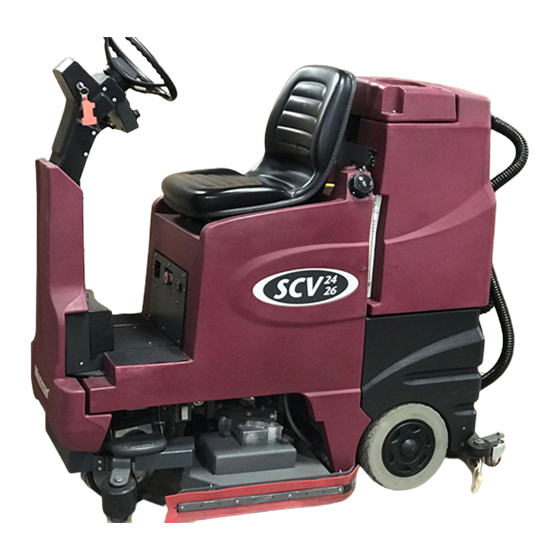
- Page 1 SCV 24/26 RIDER SCRUBBER ■ ■ ■ OPERATION SERVICE PARTS CARE...
- Page 2 This manual is furnished with each new MINUTEMAN SCV 24/26. This provides the necessary operating and preventive maintenance instructions. Operators must read and understand this manual before operating or servicing this machine. This machine was designed to give you excellent performance and efficiency. For best results and minimal cost, please follow the general guidelines below: •...
-
Page 4: Table Of Contents
TABLE OF CONTENTS Operation, Illustrations, Spare Parts, and Maintenance IMPORTANT SAFETY INSTRUCTIONS ................4 FOR SAFETY DURING OPERATION: ............4 FOR SAFETY WHEN SERVICING MAINTAINING MACHINE: .... 4 INSPECTION ...........6 ELECTRICAL...........6 BATTERIES ..........6 OPERATOR RESPONSIBILITY ....6 MACHINE OVERVIEW - FRONT..................7 MACHINE OVERVIEW - REAR ................... - Page 5 MACHINE OPERATION................. 23 MAINTENANCE SCHEDULE ................ 26 GENERAL MACHINE TROUBLESHOOTING..............27 SCV 24/26 FAULT / DIAGNOSTIC CODES ............... 29 EXPLODED VIEWS ....................... 30 MAIN ASSEMBLY I ..................30 MAIN ASSEMBLY II..................31 MAIN ASSEMBLY BOM (SEE MAIN ASSEMBLY I & II) ......32 MAINFRAME ASSEMBLY ................
- Page 6 24” DISC SCRUB DECK ASSEMBLY I ............63 24” DISC SCRUB DECK ASSEMBLY II ............64 24” DISC SCRUB DECK BOM (SEE ASSEMBLY I & II) ......65 26” DISC SCRUB DECK ASSEMBLY I ............66 26” DISC SCRUB DECK ASSEMBLY II ............67 26”...
-
Page 7: Important Safety Instructions
Do not operate this machine in flammable or explosive areas. This machine is designed solely for scrubbing dirt and dust in an indoor environment. Minuteman does not recommend using this machine in any other capacity. The following information below may cause a potential hazard to the operator and equipment. - Page 8 Do not smoke. Make sure the charger is turned off before disconnecting it from the machine. Charge the batteries in a well-ventilated area with the battery cover removed completely. Do not clean machine with a pressure washer. Authorized personnel must perform repairs and maintenance. Use Minuteman supplied replacement parts. SAVE THESE INSTRUCTIONS...
-
Page 9: Inspection
This machine is battery operated and designed to operate on 36 volts DC (3) 12-volt batteries. BATTERIES The recommended batteries are rated 210Ah (Minuteman P/N 956210). We do not recommend mixing AMP hour capacities. Any alternate battery sets can be used if they equal physical size and capacity. -
Page 10: Machine Overview - Front
MACHINE OVERVIEW - FRONT A Recovery Tank Lid G Front Drive Wheel M Rear Squeegee B Steering Wheel H Foot Step N Seat Adj. Lever C Directional Lever I Side Squeegee O Safety Latch D Tilt Steering Lever J Scrub Deck P Solution Tank Fill Port E Accelerator Pedal K Solution Tank... -
Page 11: Machine Overview - Rear
MACHINE OVERVIEW - REAR A Recovery Tank Dump Hose E Upper Control Console B Off Aisle Wand Hose Connection F Horn C Recovery Hose H Lower Control Console D Cleanout... -
Page 12: Lower Control Console
LOWER CONTROL CONSOLE 1. REGULAR SCRUB MODE When the machine is running in this mode, the machine will perform all operations. This mode can be used for day-to-day tasks under normal conditions. When the operator sets the directional switch to forward and activates the accelerator handle, the solution pump will turn on, the brushes will turn on and be lowered to the floor, as well as the rear squeegee. -
Page 13: Vacuum Only Mode
will need additional time to emulsify grease and oils that are on the floor. When the operator sets the directional switch to either the forward or reverse position and activates the accelerator lever, the solution pump will turn on, the brushes will turn on and be lowered to the floor. -
Page 14: Upper Control Console
UPPER CONTROL CONSOLE EMPTY SOLUTION TANK INDICATOR Once the solution tank has become empty the battery gauge will blink a solid 9 LEDs at a constant interval to alert the driver that the solution tank needs to be filled. LOW BATTERY INDICATOR The battery gauge bar icon will be flashing to signal the operator that the machine is almost out of power. -
Page 15: Operation Of Controls
OPERATION OF CONTROLS POWER SAVE MODE The SCV is equipped with a power save feature to conserve battery power. If the key switch power is left ON and none of the controls are activated for a period of fifteen minutes, the SCV automatically goes into “power down mode”... -
Page 16: Parking Brake
Connect the batteries according to the battery connection diagram (see diagram). The recommended batteries are 210Ah (Minuteman P/N 956210). SCRUB DECK Minuteman offers two deck types (Cylindrical and Disc) to fit your specific needs. The SCV design is... -
Page 17: Cylindrical Scrub Deck
very dynamic wherein the decks are interchangeable in a matter of minutes whenever necessary (removal of four bolts, and two quick-connects). The cylindrical brush deck has four built-in spray jets to uniformly dispense cleaning solution on the floor and a wet sweeping debris tray to collect loose objects on the floor. -
Page 18: Scrub Deck Shift
SCRUB DECK SHIFT The SCV 2426 now incorporates the new side shift feature, which allows the scrub deck to move two inches to the right to allow users to get into tighter quarters such as under shelving or cleaning close to walls. The side shift is activated by a lighted three-position rocker switch located directly in front of the drivers seat, just below the steering wheel (See figure below). -
Page 19: Installation Instructions
When installing a cylindrical deck to a machine: 1. Install brushes after the deck has been mounted to avoid flat spots on the brushes. 2. Use a piece of cardboard underneath the deck to prevent scratches to the painted surface when sliding the deck under the machine. -
Page 20: Interchanging Scrub Decks
IMPORTANT NOTE WHEN INTERCHANGING SCRUB DECKS As previously mentioned, the scrub deck brush pressure is computer controlled. However, when interchanging the two types of decks, an additional step must be taken to ensure that the controller correctly compensates the pressure for the type of deck that is currently installed. Inside the main electrical box, beneath the seat there is an Orange/Violet jumper wire (shown disconnected in Figure 1) that may or may not be connected to the terminal block, depending on the type of scrub deck that was originally ordered with the machine. -
Page 21: Side Squeegee
SIDE SQUEEGEE The side squeegees (left and right) are attached to the scrub decks. These items channel the dirty solution to the rear squeegee, helping contain the water within the machine’s cleaning path. These squeegees are raised when the scrub deck is in the raised position. The side squeegees are pre-adjusted at the factory. -
Page 22: Brush Changes On The Cylindrical Deck
Brush Changes on the Cylindrical Deck In order to change the brushes on the cylindrical deck the side squeegee must be moved in order to access the brush doors. The cylindrical deck was designed so one can change the brushes without having to realign the side squeegees. -
Page 23: Rear Squeegee
REAR SQUEEGEE The rear squeegee is the main element that acts as the conduit that transfers the spent solution into the recovery tank. A daily maintenance check of this component is essential to have optimum machine performance. The rear squeegee assembly is equipped with a universal front blade that allows the operator the option to use a slotted and a non-slotted side for specific applications. -
Page 24: Rear Squeegee Adjustment
REAR SQUEEGEE ADJUSTMENT 1. Ensure that the scrubber is on a relatively flat surface. Turn on the key switch and select the Vacuum only mode. This lowers the squeegee to the floor and turns the vacuum motor on. 2. Move the scrubber one or two feet forward slowly while someone behind the machine checks the rear squeegee blade (item 1) for uniform deflection to the floor. -
Page 25: Off-Aisle Wand (Optional)
OFF-AISLE WAND (Optional) The SCV is equipped with a ready-to-use built-in telescoping off-aisle wand system for use in hard to reach areas. By turning the pump switch ON (located on the control console, see page 11 for illustration) the off-aisle wand is ready to use in seconds. The wand is also equipped with the patented flip-flop tool that allows the operator to switch from scrub brush to squeegee tool by just rotating the tool end. -
Page 26: The Scv Rider
The SCV has four available scrub head types and sizes to fit specific applications. Please contact your Minuteman representative for specific recommendations for the correct scrub head type, size, and brush type and chemical applications. - Page 27 4. Determine the direction you need to travel by selecting forward or reverse on the Directional Switch. Vary the pressure exerted on the accelerator pedal to propel the machine at the desired speed. 5. Stepping on the Accelerator Pedal turns on the Transport, Brushes, Water Flow, Vacuum and lowers the Rear Squeegee accordingly to the Mode selected.
- Page 28 sure to tightly secure the Stopper plug and cleanout cap before continuing to operate the scrubber. 17. Refill the solution tank and continue scrubbing until the job is done or when the machine runs out of power. 18. The battery gauge bar icon will flash to signal the operator that the machine is almost out of power.
-
Page 29: Maintenance Schedule
Filter Clean Hopper on Cylindrical System • Have Minuteman check the vacuum motor carbon motor brushes once a year or after 300 operating hours. The brush motor carbon brushes should be checked every 500 hours or once a year. NOTE: Refer to the Service Manual for more detail on maintenance and service repairs. -
Page 30: General Machine Troubleshooting
Worn brushes Rotate or replace brushes Poor scrubbing Wrong brush or cleaning Consult Minuteman performance chemical Debris caught on scrub brushes Remove debris Moving machine too fast Slow down Low battery charge... - Page 31 Drive system speed controller. Check error fault codes (See service manual) No FWD/REV drive Reset machine: Turn key switch off and restart. Emergency stop switch tripped Activate switch by turning as indicated by arrows. Recovery tank full Empty recovery tank Excessive foaming in recovery Empty recovery tank.
-
Page 32: Scv 24/26 Fault / Diagnostic Codes
SCV 24/26 FAULT / DIAGNOSTIC CODES... -
Page 33: Exploded Views
EXPLODED VIEWS MAIN ASSEMBLY I... -
Page 34: Main Assembly Ii
MAIN ASSEMBLY II... -
Page 35: Main Assembly Bom (See Main Assembly I & Ii)
MAIN ASSEMBLY BOM (SEE MAIN ASSEMBLY I & II) -
Page 36: Mainframe Assembly
MAINFRAME ASSEMBLY... -
Page 37: Linkage Assembly
LINKAGE ASSEMBLY... -
Page 38: Linkage Assembly Bom
LINKAGE ASSEMBLY BOM... -
Page 39: Front Drive Assembly
FRONT DRIVE ASSEMBLY... -
Page 40: Drive Cable Guide Assembly
DRIVE CABLE GUIDE ASSEMBLY... -
Page 41: Steering Assembly I
STEERING ASSEMBLY I... -
Page 42: Steering Assembly Ii
STEERING ASSEMBLY II... -
Page 43: Steering Assembly Bom (See Str. Asm. I & Ii)
STEERING ASSEMBLY BOM (SEE STEERING ASSEMBLY I & II) -
Page 44: Solution Tank Assembly I
SOLUTION TANK ASSEMBLY I... -
Page 45: Solution Tank Assembly Ii
SOLUTION TANK ASSEMBLY II... -
Page 46: Solution Tank Assembly Bom (See Sol. Tank Assy I & Ii)
SOLUTION TANK ASSEMBLY BOM (SEE SOL. TANK ASSY I & II) -
Page 47: Seat Assembly
SEAT ASSEMBLY... -
Page 48: Electrical Panel Assembly
ELECTRICAL PANEL ASSEMBLY... -
Page 49: Recovery Tank Assembly I
RECOVERY TANK ASSEMBLY I... -
Page 50: Recovery Tank Assembly Ii
RECOVERY TANK ASSEMBLY II... -
Page 51: Recovery Tank Bom (See Rec. Tank Assy. I & Ii)
RECOVERY TANK BOM (SEE REC TANK ASSEMBLY I & II) -
Page 52: Pump Assembly
PUMP ASSEMBLY... -
Page 53: Pump Assembly Bom
PUMP ASSEMBLY BOM... -
Page 54: Rear Axle Assembly
REAR AXLE ASSEMBLY... -
Page 55: Rear Squeegee
REAR SQUEEGEE... -
Page 56: Squeegee Mechanism Assembly
SQUEEGEE MECHANISM ASSEMBLY... -
Page 57: Rear Squeegee Assembly
REAR SQUEEGEE ASSEMBLY... -
Page 58: Battery Panel Assembly (Left Hand Side)
BATTERY PANEL ASSEMBLY (LEFT HAND SIDE) -
Page 59: Battery Panel Assembly (Right Hand Side)
BATTERY PANEL ASSEMBLY (RIGHT HAND SIDE) -
Page 60: 24" Cylindrical Scrub Deck Assembly I (Items 1 - 32)
24” CYLINDRICAL SCRUB DECK ASSEMBLY I (ITEMS 1 – 32) -
Page 61: 24" Cylindrical Scrub Deck Assembly Ii (Items 33 - 63)
24” CYLINDRICAL SCRUB DECK ASSEMBLY II (ITEMS 33 – 63) -
Page 62: 24" Cylindrical Scrubdeck Bom (See Assembly I & Ii)
24” CYLINDRICAL SCRUBDECK BOM (SEE ASSEMBLY I & II) -
Page 63: 26" Cylindrical Scrub Deck Assembly I (Items 1 - 32)
26” CYLINDRICAL SCRUB DECK ASSEMBLY I (ITEMS 1 – 32) -
Page 64: 26" Cylindrical Scrub Deck Assembly Ii (Items 33 - 63)
26” CYLINDRICAL SCRUB DECK ASSEMBLY II (ITEMS 33 – 63) -
Page 65: 26" Cylindrical Scrubdeck Bom (See Assembly I & Ii)
26” CYLINDRICAL SCRUBDECK BOM (SEE ASSEMBLY I & II) -
Page 66: 24" Disc Scrub Deck Assembly I
24” DISC SCRUB DECK ASSEMBLY I... -
Page 67: 24" Disc Scrub Deck Assembly Ii
24” DISC SCRUB DECK ASSEMBLY II... -
Page 68: 24" Disc Scrub Deck Bom (See Assembly I & Ii)
24” DISC SCRUB DECK BOM (SEE ASSEMBLY I & II) -
Page 69: 26" Disc Scrub Deck Assembly I
26” DISC SCRUB DECK ASSEMBLY I... -
Page 70: 26" Disc Scrub Deck Assembly Ii
26” DISC SCRUB DECK ASSEMBLY II... -
Page 71: 26" Disc Scrub Deck Bom (See Assembly I & Ii)
26” DISC SCRUB DECK BOM (SEE ASSEMBLY I & II) -
Page 72: Cylindrical Side Squeegee (Left Side)
CYLINDRICAL SIDE SQUEEGEE (LEFT SIDE) -
Page 73: Cylindrical Side Squeegee (Right Side)
CYLINDRICAL SIDE SQUEEGEE (RIGHT SIDE) -
Page 74: Disk Side Squeegee (Left Side)
DISK SIDE SQUEEGEE (LEFT SIDE) -
Page 75: Disc Side Squeegee (Right Side)
DISC SIDE SQUEEGEE (RIGHT SIDE) -
Page 76: 24" Cylindrical Brush Assembly
BRUSH, CYL 24" STRATAGRIT 46GR 241528 BRUSH, CYL 24" STRGRIT PLUS 36 241529 BRUSH, CYL 24" 180 GR 241702 24" CYL DECK W/ SIDE SQUEEGEES, SCV 24/26 711242 BLT-HEX 3/8-16X1.00 ZP 711515 WSR-FLAT .406 X .812 X .0625 711546 WSR-HELICAL 3/8... -
Page 77: 24" Disc Brush Assembly
24” DISC BRUSH ASSEMBLY BILL OF MATERIAL ITEM PART NO. REQ'D DESCRIPTION 241601 DISK SCRUBDECK, 24" 241618 BRUSH - 12" PWR DRIVE W/ PAD HOLDER 241620 12" SCRUB BRUSH .022 NYLON 241621 12" SCRUB BRUSH .028 NYLON 241622 12" SCRUB BRUSH DYNASCRUB 500GR 241623 12"... -
Page 78: 26" Cylindrical Brush Assembly
BRUSH, CYL 26" STRATAGRIT 46GR 241538 BRUSH, CYL 26" STRGRIT PLUS 36 241539 BRUSH, CYL 26" 180 GR 241703 26" CYL DECK W/ SIDE SQUEEGEES, SCV 24/26 711242 BLT-HEX 3/8-16X1.00 ZP 711515 WSR-FLAT .406 X .812 X .0625 711546 WSR-HELICAL 3/8... -
Page 79: 26" Disc Brush Assembly
26” DISC BRUSH ASSEMBLY BILL OF MATERIAL ITEM PART NO. REQ'D DESCRIPTION 241651 DISK SCRUBDECK, 26" 241619 BRUSH - 13" PWR DRIVE W/ PAD HOLDER 241630 13" SCRUB BRUSH .022 NYLON 241631 13" SCRUB BRUSH .028 NYLON 241632 13" SCRUB BRUSH DYNASCRUB 500GR 241633 13"... -
Page 80: Plumbing Diagram
PLUMBING DIAGRAM... -
Page 81: Wiring Diagrams
WIRING DIAGRAMS... -
Page 85: Limited Warranty
Minuteman International, Inc. warrants to the original purchaser/user that this product is free from defects in workmanship and materials under normal use and service for a period of three years from date of purchase. In addition, Minuteman International, Inc. will, at its option, honor labor warranty claims for the first 36 months from date of sale, provided such claims are submitted through and approved by factory authorized repair stations.
Need help?
Do you have a question about the scv 24 and is the answer not in the manual?
Questions and answers