Hobo MicroRX Station RX210 Series Manual
Hide thumbs
Also See for MicroRX Station RX210 Series:
- Installation manual (4 pages) ,
- Installing (4 pages) ,
- Installing manual (2 pages)
Table of Contents
Advertisement
Quick Links
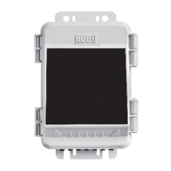
HOBO® MicroRX Station (RX210x) Manual
RX2102 model shown
HOBO MicroRX Station
Models: RX2101 MicroRX Station
RX2102 MicroRX Station with
Solar Panel
RX2103 MicroRX Water Level
Station
RX2104 MicroRX Water Level
Station with Solar Panel
Included Items:
• Grease packet
• Screws and washers
• Cable ties
Required Items:
• HOBOlink
• Smart Sensors (required for
RX2101 and RX2102; optional for
RX2103 and RX2104)
For RX2103 and RX2104 models:
One MX2001 water level sensor and
one cable:
• MX2001-01-S or MX2001-01-Ti-S
(Titanium), 9-meter/30-foot
depth)
• MX2001-02-S, 30-meter/100-foot
depth
• MX2001-03-S, 76-meter/250-foot
depth
• MX2001-04-S or MX2001-04-Ti-S
(Titanium), 4-meter/13-foot
depth
• Cable (CABLE-RWL-xxx)
Optional Items:
• AC adapter (P-AC-1)
• Ground wire (CABLE-MICRO-G)
• 2-meter tripod (M-TPB)
• 3-meter tripod (M-TPA)
• 1.5 meter mast (M-MPB)
• 1-5/8 inch U-bolts (U-BOLT-KIT2)
• Guy wire kit (M-GWA)
• 1/2 inch stake kit (M-SKA)
• Well cap (WELL-CAP-02)
23808-A
1.800.561.8187
The HOBO MicroRX Station provides continuous logging for a broad range of weather monitoring
and microclimate applications with up to five plug-and-play smart sensor inputs. In addition, the
HOBO MicroRX Water Level Station supports an easy-to-install water level sensor and integrated
flow conversion for monitoring streams, lakes, wetlands, tidal areas, groundwater, and more.
Logged data from the station is transferred at regular connection intervals to HOBOlink® web-
based software where you can check the latest conditions, view graphs, configure sensors and
alarms, set up a dashboard, download your data, or schedule data delivery via email or FTP. Inside
its weatherproof enclosure, this compact station has a built-in LCD screen to check the current
system configuration and status, start and stop logging, add and remove smart sensors, and
connect to HOBOlink on demand. The station offers two primary power source options depending
on your deployment needs: the RX2101 and RX2103 models include user-replaceable AA lithium
batteries while the RX2102 and RX2104 models are designed with a built-in solar panel and
rechargeable NiMH battery pack.
Specifications
Station
Operating Range
Smart Sensor Connectors
Smart Sensor Network Cable
Length
Smart Sensor Data Channels
Logging Rate
Time Accuracy
Battery Type/Power Source
Battery Life
www.
.com
RX2101 and RX2103: -40° to 60°C (-40° to 140°F)
RX2102 and RX2104: -20° to 60°C (-4° to 140°F)
5
100 m (328 ft) maximum
Maximum of 15 (some smart sensors use more than one data
channel; see sensor manual for details)
1 minute to 18 hours
±8 seconds per month in 0° to 40°C (32°F to 104°F) range;
±30 seconds per month in -40° to 60°C (-40° to 140°F) range
RX2102 and RX2104: Integrated 1.7 watt solar panel and NiMH
rechargeable battery pack; optional AC power adapter (P-AC-1) or
external solar panel (SOLAR-xW) can be used in place of integrated
solar panel
RX2101 and RX2103: 6 AA 1.5 V lithium batteries or AC power
adapter (P-AC-1)
RX2102 and RX2104:
Typical 3–5 years when operated in the temperature range -20° to
40°C (-4° to 104°F); operation outside this range will reduce the
battery service life.
Maximum connection rates with built-in solar panel, in full sun:
• 10 minute connections year round for latitudes less than ±40°
• 10 minute connections through three seasons in other regions,
reduced to 30 minute connections in winter
Maximum connection rates with external 5W or 15W solar panels:
• 10 minute connections year round, in full sun
• Connection rate with external solar panels may be less if
deployed in partial sun
Battery life without solar recharging, with hourly connections and
1 minute logging:
• RX2102: 3 months
• RX2104: 2 months
RX2101 and RX2103:
Battery life with daily connections:
• RX2101: 1 year with 1 minute logging
• RX2103: 1 year with 2 minute logging
Battery life with hourly connections and 1 minute logging:
• RX2101: 3 months
• RX2103: 2 months
Note: Deployments in areas with weak cellular strength could
reduce battery life.
information@itm.com
Advertisement
Table of Contents

Related Manuals for Hobo MicroRX Station RX210 Series


Summary of Contents for Hobo MicroRX Station RX210 Series
- Page 1 HOBO® MicroRX Station (RX210x) Manual The HOBO MicroRX Station provides continuous logging for a broad range of weather monitoring and microclimate applications with up to five plug-and-play smart sensor inputs. In addition, the HOBO MicroRX Water Level Station supports an easy-to-install water level sensor and integrated flow conversion for monitoring streams, lakes, wetlands, tidal areas, groundwater, and more.
- Page 2 HOBO MicroRX Station Manual Specifications (continued) Memory 16 MB, 1 million measurements, continuous logging 5.3 cm Alarm Notification Latency Logging interval plus 2–4 minutes, typical (2.1 in.) Enclosure Access Hinged door secured by two latches with eyelets for use with user- 3.2 cm...
- Page 3 HOBO MicroRX Station Manual Specifications (continued) Pressure (Absolute) and Water Level Measurements MX2001-03-S Operation Range 0 to 850 kPa (0 to 123.3 psia); approximately 0 to 76.5 m (0 to 251 ft) of water depth at sea level, or 0 to 79.5 m (0 to 262 ft) of water at...
-
Page 4: Table Of Contents
HOBO MicroRX Station Manual Table of Contents Micro SIM Card Select Device Components and Operation ..........4 Button LCD Operation ................5 USB Port Setting up the Station ..............7 Start/ 1. Log in to HOBOlink.............. 7 Stop 2. Register the station............. 7 Button 3. -
Page 5: Lcd Operation
HOBO MicroRX Station Manual Station Door: This is the protective, hinged door covering the Water Level Sensor Port: Use this port to connect a water level LCD and electronics. The station serial number and device key sensor in the RX2103 and RX2104 models (see Setting up the needed for HOBOlink registration are located on the inside of Station). - Page 6 HOBO MicroRX Station Manual This shows the strength of the cellular signal; the more bars there are, the stronger the signal. This will blink while connecting to HOBOlink. When the station is attempting to connect or is currently connected to HOBOlink, “Connection” flashes on the LCD. After the connection is complete, “Last Connection”...
-
Page 7: Setting Up The Station
HOBO MicroRX Station Manual This is a numerical code that appears when a system fault has occurred. You may need to provide this code to Onset Technical Support. See Troubleshooting for details. This is the version number of the station firmware. It only appears when powering up the device. -
Page 8: Remove The Cable Channel. Make A Note Of How The Cable Channel Is Oriented When Removing It
HOBO MicroRX Station Manual Remove the cable channel. Make a note of how the cable channel is oriented when removing it. Secure the cable with the enclosed screws Cable channel 5. Install the water level sensor if applicable (RX2103 and RX2104 models). -
Page 9: Grease And Reinstall The Cable Channel
HOBO MicroRX Station Manual 7. Grease and reinstall the cable channel. 8. Plug in the battery and wait for the station to connect to HOBOlink. a. Use the integrated plugs to fill any unused holes. Bend the plugs up so that you can push them into the holes. -
Page 10: Configure The Station In Hobolink
HOBO MicroRX Station Manual 9. Configure the station in HOBOlink. In HOBOlink, click Devices, then RX Devices and click the icon next to your station. Use the configuration screens in HOBOlink to finish setting up the station, starting with General Configuration (the nickname, time zone, and image for the station). -
Page 11: Start Logging
HOBO MicroRX Station Manual h. Click Save. You can also click Next to move from one smart sensor to the next and save the sensor configuration. Clicking Back does not save the configuration changes. Important: Do not configure the water level and water flow channels yet. -
Page 12: Obtain A Reference Water Level Reading
HOBO MicroRX Station Manual Water Flow Configuration 11. Obtain a reference water level reading (RX2103 and RX2104 models). a. Select Water Flow from the Configuration menu. Make sure the water level sensor is deployed in its final location and the station is logging. Take a reference level reading, measuring the water level from your reference point. -
Page 13: Setting System And Sensor Alarms
HOBO MicroRX Station Manual 3. Follow the instructions on the screen to select the name, 4. For Battery Low and Sensor Failure alarms: format, time zone, and time frame, and then the devices a. Under Device, select the Battery Low and/or Sensor and sensors to include in the export. -
Page 14: Setting Up Water Level And Water Flow Channels In Hobolink (Rx2103 And Rx2104 Models)
HOBO MicroRX Station Manual 7. Click Save. Changes will take effect the next time the station If a water level sensor is not physically connected to an RX2103 connects to HOBOlink. or RX2104 station, barometric pressure will be the only channel logged as that sensor is inside the station (aside from any 8. -
Page 15: Setting Up A Water Flow Channel For A V-Notch Weir
HOBO MicroRX Station Manual • The weir should be between 0.8 and 2 mm (0.03 and 0.08 6. Select the appropriate water density for your deployment location. inches) thick in the v-notch. If the bulk of the weir is thicker than 2 mm (0.08 inches), the downstream edge of 7. -
Page 16: Setting Up A Water Flow Channel For A General Flume
HOBO MicroRX Station Manual For other types of flumes, such as this example diagram Setting up a Water Flow Channel for a General Flume where the water level (or H) is being measured from the If you are using a flume along with the water level sensor, then... -
Page 17: Starting And Stopping Logging
HOBO MicroRX Station Manual • If you entered the reference water level in feet when the rating curve for that site at https://waterwatch.usgs.gov/?id=mkrc. setting up the water level channel, then the points in the table must be entered in feet and cfs. -
Page 18: Managing Connections To Hobolink
HOBO MicroRX Station Manual 3. Open the station door. occurred at 10:05. If you use the Connect button on the station to connect to HOBOlink at 10:15, the next connection will then 4. Unplug any smart sensors you wish to remove. Plug in any be about 11:15 based on the one-hour connection interval. -
Page 19: Guidelines For The Rx2102 And Rx2104 Models
HOBO MicroRX Station Manual • Make sure all cables and wires are fastened securely and a 5 cm (2 inch) well. Otherwise, you will need to find another method of attaching the cable at the top of your routed through the cable channel. Any empty holes in the well so that the sensor stays in position. -
Page 20: Installing The Grounding Wire
HOBO MicroRX Station Manual • Be very careful not to exceed the burst pressure for the • Grease the sides and bottom of the cable channel and the sensor. The pressure sensor will burst if the maximum portion of the cables in the cable channel with a small depth is exceeded (see Specifications). -
Page 21: Battery Information For Rx2102 And Rx2104 Models
HOBO MicroRX Station Manual Deployments in extremely cold or hot temperatures, a logging WARNING: Do not cut open, incinerate, heat above 85°C interval faster than 1 minute, or a sampling interval faster than (185°F), or recharge the lithium batteries. The batteries may 15 seconds can impact battery life. - Page 22 © 2019 Onset Computer Corporation. All rights reserved. Onset, HOBO, HOBOlink, and HOBOware are trademarks or registered trademarks of Onset Computer Corporation. All other trademarks are the property of their respective companies.
Need help?
Do you have a question about the MicroRX Station RX210 Series and is the answer not in the manual?
Questions and answers