
Subscribe to Our Youtube Channel
Related Manuals for Fujitsu ARYG72LHTA


Summary of Contents for Fujitsu ARYG72LHTA
- Page 1 AIR CONDITIONER Duct type DESIGN & TECHNICAL MANUAL INDOOR ARYG72LHTA ARYG90LHTA OUTDOOR AOYG72LRLA AOYG90LRLA DR_AR012EF_05 2018.07.13...
- Page 2 Notices: • Product specifications and design are subject to change without notice for future improvement. • For further details, please check with our authorized dealer. Copyright © 2017, 2018 Fujitsu General Limited. All rights reserved.
-
Page 3: Table Of Contents
CONTENTS Part 1. INDOOR UNIT................1 1. Product features....................2 1-1. System outline .........................2 2. Specifications....................3 3. Dimensions....................4 3-1. Models: ARYG72LHTA and ARYG90LHTA..............4 3-2. Installation space requirement ..................5 3-3. Maintenance space requirement..................6 4. Wiring diagrams ....................7 4-1. Model: ARYG72LHTA......................7 4-2. Model: ARYG90LHTA......................8 5. - Page 4 CONTENTS (continued) Part 2. OUTDOOR UNIT..............53 1. Specifications....................54 2. Dimensions....................55 2-1. Models: AOYG72LRLA and AOYG90LRLA..............55 3. Installation space ..................56 3-1. Models: AOYG72LRLA and AOYG90LRLA..............56 4. Refrigerant circuit ..................59 4-1. Models: AOYG72LRLA and AOYG90LRLA..............59 5. Wiring diagrams ..................60 5-1. Models: AOYG72LRLA and AOYG90LRLA..............60 6.
-
Page 5: Part 1. Indoor Unit
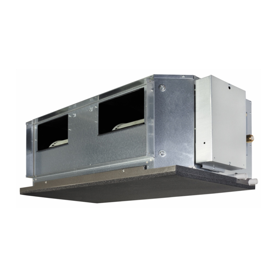
Part 1. INDOOR UNIT DUCT TYPE: ARYG72LHTA ARYG90LHTA... -
Page 6: Product Features
1. Product features 1-1. System outline Indoor unit Outdoor unit Circuit breaker (over current) Earth leakage breaker Power supply φ1 230V~50Hz : Power supply [Outdoor Unit] ( Circuit breaker : Piping ( (over current) : Transmission line [O.U. - I.U] ( Earth leakage breaker : Power supply [Indoor Unit] (... -
Page 7: Specifications
2. Specifications Duct Type Inverter heat pump Model name ARYG72LHTA ARYG90LHTA Power supply 230 V ~ 50 Hz Available voltage range 198—264 V 19.0 22.0 Rated Btu/h 64,800 75,000 Cooling 8.40 —20.90 10.30—24.20 Min.—Max. Btu/h 28,600 —71,300 35,100 —82,500 Capacity 22.4... -
Page 8: Dimensions
3. Dimensions 3-1. Models: ARYG72LHTA and ARYG90LHTA Unit: mm Control box Gas pipe Drain port Liquid pipe Side view (L) Top view Side view (R) Front view Rear view - 4 - 3-1. Models: ARYG72LHTA and ARYG90LHTA 3. Dimensions... -
Page 9: Installation Space Requirement
3-2. Installation space requirement Provide sufficient installation space for product safety. ¢ Models: ARYG72LHTA and ARYG90LHTA • Installation by which service space is made on top of the unit (recommended): Unit: mm 150 or more 500 or more 20 or more... -
Page 10: Maintenance Space Requirement
For future maintenance and service access, provide sufficient maintenance space. NOTE: Do not place any wiring or illumination in the maintenance space, as they will impede ser- vice. ¢ Models: ARYG72LHTA and ARYG90LHTA Unit: mm Service access 500 or more... -
Page 11: Wiring Diagrams
4. Wiring diagrams 4-1. Model: ARYG72LHTA I/O PCB, WLAN adapter, Converter etc. - 7 - 4-1. Model: ARYG72LHTA 4. Wiring diagrams... -
Page 12: Model: Aryg90Lhta
4-2. Model: ARYG90LHTA I/O PCB, WLAN adapter, Converter etc. - 8 - 4-2. Model: ARYG90LHTA 4. Wiring diagrams... -
Page 13: Capacity Table
Airflow Rate (AFR): For cooling capacity: Total Capacity (TC), Sensible Heat Capacity (SHC), and Input Power (IP) For heating capacity: Total Capacity (TC) and Input Power (IP) 5-1. Cooling capacity ¢ Model: ARYG72LHTA 4,300 Indoor temperature °CDB °CWB... -
Page 14: Heating Capacity
5-2. Heating capacity NOTE: Values mentioned in the table are calculated based on the maximum capacity. ¢ Model: ARYG72LHTA 4,300 Indoor temperature °CDB °CDB °CWB 10.58 5.57 10.32 5.68 10.07 5.80 9.82 5.91 9.57 6.02 16.21 6.42 15.83 6.56 15.44 6.69... -
Page 15: Fan Performance
6. Fan performance 6-1. Fan performance curve ¢ Model: ARYG72LHTA Fan performance curve_1 SP mode15 Hi (SP mode15) upper limit Qu (SP mode15) Normal SP Hi (Normal SP) upper limit SP mode15 lower limit Qu (Normal SP) Normal SP lower limit... - Page 16 Characteristics of air volume and capacity • Cooling 2,000 2,500 3,000 3,500 4,500 5,000 4,000 [l/s] 1,250 1,389 1,111 Airflow • Heating 2,000 2,500 3,000 3,500 4,500 5,000 4,000 1,250 1,389 [l/s] 1,111 Airflow - 12 - 6-1. Fan performance curve 6.
- Page 17 ¢ Model: ARYG90LHTA Fan performance curve_1 Hi (SP mode20) SP mode20 upper limit Qu (SP mode20) SP mode20 lower limit Normal SP Hi (Normal SP) upper limit Qu (Normal SP) Normal SP lower limit 2,000 2,500 3,000 3,500 4,500 5,000 4,000 1,250 1,389...
- Page 18 Characteristics of air volume and capacity • Cooling 2,000 2,500 3,000 3,500 4,500 5,000 4,000 [l/s] 1,250 1,389 1,111 Airflow • Heating 2,000 2,500 3,000 3,500 4,500 5,000 4,000 1,250 1,389 [l/s] 1,111 Airflow ¢ Automatic airflow adjustment procedures 1.
-
Page 19: Airflow
6-2. Airflow ¢ Model: ARYG72LHTA Cooling Fan speed Airflow 4,300 HIGH 1.195 2,531 3,900 1,083 2,296 3,450 2,031 3,000 QUIET 1,766 Heating Fan speed Airflow 4,300 HIGH 1.195 2,531 3,900 1,083 2,296 3,450 2,031 3,000 QUIET 1,766 - 15 - 6-2. - Page 20 ¢ Model: ARYG90LHTA Cooling Fan speed Airflow 4,300 HIGH 1.195 2,531 3,900 1,083 2,296 3,450 2,031 3,000 QUIET 1,766 Heating Fan speed Airflow 4,300 HIGH 1.195 2,531 3,900 1,083 2,296 3,450 2,031 3,000 QUIET 1,766 - 16 - 6-2.
-
Page 21: Operation Noise (Sound Pressure)
7. Operation noise (sound pressure) 7-1. Noise level curve ¢ Model: ARYG72LHTA Cooling Heating NC-65 NC-65 NC-60 NC-60 NC-55 NC-55 High NC-50 NC-50 High NC-45 NC-45 NC-40 NC-40 Quiet NC-35 NC-35 NC-30 NC-30 Quiet NC-25 NC-25 NC-20 NC-20... -
Page 22: Sound Level Check Point
7-2. Sound level check point Product Measuring duct Measuring duct (Set the static pressure as rating in this area.) Microphone Microphone Front view Side view - 18 - 7-2. Sound level check point 7. Operation noise (sound pressure) -
Page 23: Electrical Characteristics
8. Electrical characteristics Model name ARYG72LHTA ARYG90LHTA Voltage 230 ~ Power supply Frequency Max operating current Circuit breaker current Power cable Wiring spec. *1 Connection cable *2 Limited wiring length *1: Selected sample based on Japan Electrotechnical Standards and Codes Committee E0005. As the regulations of wire size and circuit breaker differ in each country or region, select appropriate de- vices complied to the regional standard. -
Page 24: Safety Devices
9. Safety devices Model Type of protection Protection form ARYG72LHTA ARYG90LHTA 250 V, 3.15 A Circuit protection Current fuse (PCB*) 250 V, 10 A 250 V, 20 A Fan motor protection Current protection 12.9 A 19.3 A *: Printed Circuit Board - 20 - 9. -
Page 25: External Input And Output
10. External input and output CN71 Rotary switch (Drain pump) (Float switch) CN47 (External out) (Remote sensor) CN65 (External in/out PCB) Fig. External input and output PCB CN48 (IR receiver) Fig. Indoor unit PCB Terminal (External in) External Input connect kit External input External output Connector Input select... -
Page 26: 10-1.External Input
10-1. External input • “Operation/Stop” mode or "Forced stop" mode can be selected with function setting of indoor unit. • A twisted pair cable (22AWG) should be used. Maximum length of cable is 150 m. • The wire connection should be separate from the power cable line. ¢... -
Page 27: 10-2.External Output
10-2. External output Use an external output cable with appropriate external dimension, depending on the number of ca- bles to be installed. ¢ Indoor unit • A twisted pair cable (22AWG) should be used. Maximum length of cable is 25 m. •... -
Page 28: 10-3.Combination Of External Input And Output
10-3. Combination of external input and output By combining the function setting of the indoor unit and rotary switch setting of the External input and output PCB, you can select various combinations of functions. Combination examples of external input and output are as follows: External input External input Function... - Page 29 ¢ Input signal type • Indoor unit Input signal type is only "Edge". Edge • External input and output PCB The input signal type can be selected. Signal type (edge or pulse) can be switched by the DIP switch 2 (SW2) on the External input and output PCB.
-
Page 30: 10-4.Details Of Function
10-4. Details of function ¢ Control input function When function setting is "Operation/Stop" mode 1 • In the case of "Edge" input Rotary SW of Function External input and External input Input signal Command setting / output PCB Off → On Operation Input of indoor unit Terminal... - Page 31 When function setting is "Forced stop" mode • In the case of "Edge" input Rotary SW of Function External input and External input Input signal Command setting / output PCB Off → On Forced stop Input of indoor unit Terminal On →...
- Page 32 When function setting is "Operation/Stop" mode 2 • In the case of "Edge" input Rotary SW of Function External input and External input Input signal Command setting / output PCB Off → On Operation Input of indoor unit Terminal Stop (R.C.
- Page 33 ¢ Forced thermostat off function Function Rotary SW of External External input Input signal Command setting / input and output PCB 60-00 / 2 Off → On Thermostat off 60-09 / B External input and output Input 1 60-10 / C Normal On →...
- Page 34 ¢ Error status Function Rotary SW of External External output Output signal Command setting / input and output PCB Low → High Error 60-09 / B Output of indoor unit CN47 High → Low Normal Off → On Error 60-00 / 2 Output 1 On →...
- Page 35 ¢ External heater output Function Rotary SW of External External output Output signal Command setting / input and output PCB Low → High Heater on 60-11 / D Output of indoor unit CN47 High → Low Heater off 60-00 / 2 Off →...
-
Page 36: Remote Controller
11. Remote controller 11-1. Wired remote controller ¢ Overview a LED lamp (Operation indicator) Lights while the indoor unit is operating. Blinks when an error occurred. b FAN button Each time the button is pressed, fan speed switches as follows: Auto Quiet High... - Page 37 ¢ System diagram 1 remote controller: 2 remote controllers: Indoor unit Indoor unit A, B, C: Remote controller cable A ≤ 500 m;B + C ≤ 500 m Primary Secondary Remote controller Remote controllers ¢ Electrical wiring 1 remote controller: 2 remote controllers: Indoor unit Indoor unit...
- Page 38 ¢ Specifications Dimensions and other specifications on the wired remote controller are as follows. Unit: mm Hole: 9 × 4.5 Hole: 6 × 4.5 Hole: 12.5 × 4.5 Front view Side view Rear view Size (H × W × D) 120 ×...
-
Page 39: Function Settings
NOTE: Incorrect settings can cause a product malfunction. 12-1. Function settings on indoor unit ¢ Models: ARYG72LHTA and ARYG90LHTA By using some components on the PCB, you can change the function settings. Related components on the PCB and the applicable settings... - Page 40 DIP switch setting • Remote controller address setting (SW100) When operating a number of indoor units by using a wired remote controller, DIP switch set- ting for assigning unit number to each indoor unit is required. DIP switches are normally set to make the unit number 00. Remote DIP switch number controller...
-
Page 41: 12-2.Function Settings By Using Remote Controller
12-2. Function settings by using remote controller Some function settings can be changed on the remote controller. After confirming the setting proce- dure and the content of each function setting, select appropriate functions for your installation envi- ronment. ¢ Remote controller address setting ... - Page 42 Setting the remote controller address manually NOTES: • Perform manual address setting only when setting the address with an arbitrary number. Indoor unit remote controller address setting is necessary. Set the remote controller address of indoor units connected by the same remote controller cable within a range of 1 to 9 and A (10) to F (15) so that there is no duplication.
- Page 43 Resetting the manual address setting number To activate the address setting mode, hold down the three buttons of “MENU”, “<“, and “EN- TER” at the same time for 2 seconds or longer. Menu 2 setting screen is displayed. Select the “14” in Menu 2 settings. Then press the “ENTER” button. To reset address, select “1: Reset”...
- Page 44 ¢ Remote controller master/slave setting NOTE: Set only one Master remote controller. To activate the address setting mode, hold down the three buttons of “MENU”, “<“, and “EN- TER” at the same time for 2 seconds or longer. Menu 2 setting screen is displayed. Select the “06”...
- Page 45 ¢ Setting procedure by using wired remote controller The function number and the associated setting value are displayed on the LCD of the remote con- troller. Follow the instructions written in the local setup procedure supplied with the remote controller, and select appropriate setting according to the installation environment.
- Page 46 Pressing the "+" or "-" button, to select the setting number. Then press the "ENTER" button. Setting number Example: Function number 30 Setting number 01 Error Good ・When the data was not set up on the indoor unit ・When the data was normally set up on the indoor unit. (”...
- Page 47 ¢ Contents of function setting Each function setting listed in this section is adjustable in accordance with the installation environ- ment. NOTE: Setting will not be changed if invalid numbers or setting values are selected. Function setting list Function no. Functions Filter sign Static pressure...
- Page 48 2) Static pressure Select the appropriate static pressure according to the installation conditions. Function number Setting value Setting description Factory setting 50 Pa 60 Pa 70 Pa 80 Pa 90 Pa 100 Pa 110 Pa 120 Pa 130 Pa 140 Pa 150 Pa 160 Pa 170 Pa...
- Page 49 4) Room temperature control for wired remote controller sensor Depending on the installed environment, correction of the wire remote temperature sensor may be required. Select the appropriate control setting according to the installed environment. To change this setting, set Function 42 to Both “01”. Ensure that the Thermo Sensor icon is displayed on the remote controller screen.
- Page 50 7) Cold air prevention This setting is to disable the cold air prevention function during heating operation. When disabled, the fan setting will always follow the setting on the remote controller. (Excluding defrost mode) Function number Setting value Setting description Factory setting Enable ♦...
- Page 51 11) Indoor unit fan control for energy saving for cooling Enables or disables the power-saving function by controlling the indoor unit fan rotation when the outdoor unit is stopped during cooling operation. Function number Setting value Setting description Factory setting Disable Enable Remote controller...
-
Page 52: Accessories
13. Accessories Part name Exterior Q’ty Part name Exterior Q’ty Operating manual Coupler heat insulation (For indoor unit) (small) Operating manual Cable tie (CD-ROM) (large) Operating manual Cable tie (For remote controller) (medium) Installation manual Cable tie (For indoor unit) (small) Installation manual Remote controller... -
Page 53: Optional Parts
14. Optional parts 14-1. Controllers Exterior Part name Model name Summary Easy finger touch operation with LCD Wired remote panel. Backlit LCD enables easy UTY-RNRYZ* controller operation in a dark room. Wire type: Non-polar 2-wire High visibility and easy operation. Room temperature can be accurately Wired remote controlled using the built-in thermo... - Page 54 Exterior Part name Model name Summary IR receiver kit with wireless Unit control is performed by wireless UTY-LBTYM remote remote controller. controller NOTE: Available functions may differ by the remote controller. For details, refer to the operation manual. - 50 - 14-1.
-
Page 55: 14-2.Others
14-2. Others Exterior Part name Model name Summary Thermo-sensor for sensing the Remote sensor UTY-XSZX temperature of arbitrary place in the unit room. Long-life filter can be mounted to the Long-life filter UTD-LFKA indoor unit. Optional drain lift up mechanism Drain pump unit UTZ-PX1NAB allows more flexible installation. - Page 56 Exterior Part name Model name Summary Split system This converter is required when converter UTY-VTGXV connecting single split system to VRF (AC power network system. supply) Air conditioner switching can be External switch UTY-TERX controlled by connecting other external controller sensor switches.
-
Page 57: Part 2. Outdoor Unit
Part 2. OUTDOOR UNIT SINGLE TYPE: AOYG72LRLA AOYG90LRLA... -
Page 58: Specifications
1. Specifications Type Inverter heat pump Model name AOYG72LRLA AOYG90LRLA Power supply 3N 400 V ~ 50 Hz Available voltage range 342—456 V Starting current 11.5 14.1 Cooling 5.99 7.24 Input power Rated Heating 6.12 7.65 Rated 11.2 13.5 Cooling Max. -
Page 59: Dimensions
2. Dimensions 2-1. Models: AOYG72LRLA and AOYG90LRLA Unit: mm Top view 1,080 Terminal blocks (Power) Front view Side view Rear view Bottom view - 55 - 2-1. Models: AOYG72LRLA and AOYG90LRLA 2. Dimensions... -
Page 60: Installation Space
3. Installation space 3-1. Models: AOYG72LRLA and AOYG90LRLA ¢ Space requirement Provide sufficient installation space for product safety. Single outdoor unit installation • When the upper space is open: Unit: mm When there are obstacles at the rear only. When there are obstacles at the rear and sides. - Page 61 Multiple outdoor unit installation NOTES: • Provide at least 100 mm of space between the outdoor units if multiple units are installed. • When routing the piping from the side of an outdoor unit, provide space for the piping. •...
- Page 62 Outdoor unit installation in multi-row Unit: mm Single parallel unit arrangement Multiple parallel unit arrangement 100 or 500 or more more 2,000 or more 3,000 or more 600 or more 600 or more 1,000 or more 1,500 or more NOTES: •...
-
Page 63: Refrigerant Circuit
4. Refrigerant circuit 4-1. Models: AOYG72LRLA and AOYG90LRLA Pressure 25.4mm (1in) Check Valve Pressure sensor (High) 3-WAY Valve 4-WAY Pressure Valve Pressure sensor switch (Low) Muffler Strainer Expansion Valve 12.7mm (1/2in) 3-WAY Valve - 59 - 4-1. Models: AOYG72LRLA and AOYG90LRLA 4. -
Page 64: Wiring Diagrams
5. Wiring diagrams 5-1. Models: AOYG72LRLA and AOYG90LRLA - 60 - 5-1. Models: AOYG72LRLA and AOYG90LRLA 5. Wiring diagrams... -
Page 65: Capacity Compensation Rate For Pipe Length And Height Difference
6. Capacity compensation rate for pipe length and height difference Height difference H Indoor unit is higher than outdoor unit Indoor unit is lower than outdoor unit Outdoor unit Indoor unit Outdoor unit Indoor unit Connection pipe Connection pipe 6-1. Model: AOYG72LRLA NOTE: Values mentioned in the table are calculated based on the maximum capacity. -
Page 66: Model: Aoyg90Lrla
6-2. Model: AOYG90LRLA NOTE: Values mentioned in the table are calculated based on the maximum capacity. Pipe length (m) COOLING Indoor — — — — 0.898 0.874 0.850 0.826 0.803 0.780 0.756 0.732 unit is — — — 0.938 0.913 0.889 0.864 0.840 0.817 0.793 0.769 0.744 higher —... -
Page 67: Additional Charge Calculation
7. Additional charge calculation 7-1. Model: AOYG72LRLA Refrigerant type R410A Factory charge amount 5,600 ¢ Refrigerant charge 30 or Total pipe length less (Max.) 110 g/m Additional 1,100 2,200 3,300 4,400 5,500 6,600 7,700 charge amount 7-2. Model: AOYG90LRLA Refrigerant type R410A Factory charge amount 7,100... -
Page 68: Airflow
8. Airflow 8-1. Model: AOYG72LRLA Cooling Airflow 8,400 2,334 4,944 Heating Airflow 8,400 2,334 4,944 8-2. Model: AOYG90LRLA Cooling Airflow 8,400 2,334 4,944 Heating Airflow 9,000 2,500 5,297 - 64 - 8-1. Model: AOYG72LRLA 8. Airflow... -
Page 69: Operation Noise (Sound Pressure)
9. Operation noise (sound pressure) 9-1. Noise level curve ¢ Model: AOYG72LRLA Cooling Heating NC-65 NC-65 NC-60 NC-60 NC-55 NC-55 NC-50 NC-50 NC-45 NC-45 NC-40 NC-40 NC-35 NC-35 NC-30 NC-30 NC-25 NC-25 NC-20 NC-20 NC-15 NC-15 1,000 2,000 4,000 8,000 1,000... -
Page 70: Sound Level Check Point
9-2. Sound level check point Rear Microphone Microphone Airflow Side view Rear view NOTE: Detailed shape of the actual outdoor unit might be slightly different from the one illustrated above. - 66 - 9-2. Sound level check point 9. Operation noise (sound pressure) -
Page 71: Electrical Characteristics
10. Electrical characteristics Model name AOYG72LRLA AOYG90LRLA Voltage 3N 400 ~ Power supply Frequency Max operating current 13.3 14.6 Circuit breaker current Power cable Cross-sectional Wiring spec. *1 area Connection cable *2 Limited wiring length *1: Selected sample based on Japan Electrotechnical Standards and Codes Committee E0005. As the regulations of wire size and circuit breaker differ in each country or region, select appropriate de- vices complied to the regional standard. -
Page 72: Safety Devices
11. Safety devices Model Type of Protection form protection AOYG72LRLA AOYG90LRLA Current protector (Filter PCB) 500 V, 45 A × 3 Circuit protection Current fuse (Main PCB) 250 V, 10 A Current fuse (Terminal) 250 V, 20 A 115±15 °C Activate Fan motor stop Fan motor... -
Page 73: External Input And Output
12. External input and output With using external input and output functions, this product can be operated inter-connectedly with an external device. Connector Input Output Remarks CN131 Low noise mode — CN132 Peak cut mode — See external input/output settings for details. - Page 74 ¢ Peak cut mode By performing following on-site work, operation that suppresses the current value can be enabled: The air conditioner is set to the “Peak cut mode” when closing the contact input of a commercial timer or on/off switch to a connector on the control PCB of the outdoor unit. •...
-
Page 75: 12-2.External Output
12-2. External output With using external output function, some status signals are transmitted to the control PCB, and the related LED lamp indicates the status of this product. ¢ Error status output Signal on air conditioner error status is generated when a malfunction occurs. •... - Page 76 ¢ Compressor status output Signal on compressor operation status is generated when the compressor is running. • Circuit diagram example (CN137) • 1: Power supply Outdoor unit Voltage (Vcc): DC 24 V or less Connected unit control PCB • 2: Load Connector DC 500 mA or less Power...
-
Page 77: Function Settings
13. Function settings Perform appropriate function setting locally according to the installation environment. NOTE: Incorrect settings can cause a product malfunction. CAUTION • Before setting up the switch buttons, discharge the static electricity from your body. • Never touch the terminals or the patterns on the parts that are mounted on the PCB. 13-1. - Page 78 LED lamp Function or operation method Lights on while power on. (1) POWER/MODE Green Local setting in outdoor unit or error code is displayed with blink. (2) ERROR Blinks during error operation. (3) PUMP DOWN (L1) Orange Lights on during pump down operation. LOW NOISE MODE Lights on during “Low noise mode”...
-
Page 79: 13-2.Local Setting Procedure
13-2. Local setting procedure NOTE: Before performing the function setting, be sure to stop the operation of the air conditioner. ¢ Low noise mode Press the MODE switch button (SW107) for 3 seconds or more to switch to “Local setting mode”. - Page 80 ¢ Peak cut mode Press the MODE switch button (SW107) for 3 seconds or more to switch to “Local setting mode”. After confirming the LED lamp of POWER/MODE blinks 9 times, press the ENTER switch but- ton (SW109). PUMP POWER LOW NOISE PEAK CUT DOWN...
-
Page 81: Check And Test
14. Check and test 14-1. Test run ¢ Pre-test run check items Check column Check item Is the outdoor unit securely installed? Have you performed gas leakage inspection? (Connection joints of various pipes (flange connection, brazing)) Is the heat insulation done completely? (Gas pipe, liquid pipe, drain hose extension on indoor unit side etc) Is the water discharging from drain without any problems? Are the cables connected correctly? - Page 82 2. Press the ENTER button for more than 3 seconds. PUMP PEAK POWER ERROR DOWN NOISE MODE (L1) (L2) (L3) (L4) (L5) (L6) ○ ○ ○ ○ ○ ○ Blink Blink 3. Press the SELECT button, LED of the test run mode Switched between "COOL " and "HEAT". •...
-
Page 83: 14-2.Error Code
14-2. Error code If an error occurs, the LED will light up to display the error location and the error code. ¢ Error display mode Display when an error occurs. PUMP PEAK POWER ERROR DOWN NOISE MODE (L1) (L2) (L3) (L4) (L5) (L6) -
Page 84: 14-3.Pump Down
14-3. Pump down WARNING • Never touch electrical components such as the terminal blocks except the button on the display board. It may cause a serious accident such as electric shock. • During the pump-down operation, make sure that the compressor is turned off before you re- move the refrigerant piping. - Page 85 5. When LED display changes as shown in the below figure, close the 3-way valve on the gas pipe side tightly. PUMP PEAK POWER ERROR DOWN NOISE MODE (L1) (L2) (L3) (L4) (L5) (L6) ● ○ ● ○ ○ ○ ○...
-
Page 86: Accessories
15. Accessories Part name Exterior Q’ty Part name Exterior Q’ty Installation manual Joint pipe B Drain pipe Push mount cable tie Drain cap Grommet edging Joint pipe A - 82 - 15. Accessories... -
Page 87: Optional Parts
16. Optional parts Exterior Part name Model name Summary External Use to operate the external input and UTY-XWZXZ3 connect kit output functions of outdoor unit. - 83 - 16. Optional parts...
Need help?
Do you have a question about the ARYG72LHTA and is the answer not in the manual?
Questions and answers