Fujitsu AOYG72LRLA Installation Manual
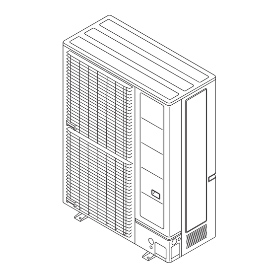
Outdoor unit
Hide thumbs
Also See for AOYG72LRLA:
- Design & technical manual (343 pages) ,
- Service instruction (110 pages) ,
- Service manual (28 pages)
Table of Contents
Advertisement
Quick Links
AIR CONDITIONER
INSTALLATION MANUAL
OUTDOOR UNIT
For authorized service personnel only.
INSTALLATIONSANLEITUNG
AUSSENGERÄT
Nur für autorisiertes Fachpersonal.
MANUEL D'INSTALLATION
UNITÉ EXTÉRIEUR
Pour le personnel de service agrée uniquement.
MANUAL DE INSTALACIÓN
UNIDAD EXTERIOR
Únicamente para personal de servicio autorizado.
MANUALE D'INSTALLAZIONE
UNITÀ ESTERNA
A uso esclusivo del personale tecnico autorizzato.
ΕΓΧΕΙΡΙΔΙΟ ΕΓΚΑΤΑΣΤΑΣΗΣ
ΕΞΩΤΕΡΙΚΗ ΜΟΝΑΔΑ
Μόνο για εξουσιοδοτημένο τεχνικό προσωπικό.
MANUAL DE INSTALAÇÃO
UNIDADE EXTERIOR
Somente para o pessoal do serviço técnico autorizado.
РУКОВОДСТВО ПО УСТАНОВКЕ
ВНЕШНИЙ МОДУЛЬ
Только для авторизованного обслуживающего персонала.
KURULUM KILAVUZU
DIŞ ÜNİTE
Yalnızca yetkili servis personeli için.
PART No. 9380545231
Advertisement
Table of Contents

Subscribe to Our Youtube Channel
Related Manuals for Fujitsu AOYG72LRLA


Summary of Contents for Fujitsu AOYG72LRLA
- Page 1 AIR CONDITIONER INSTALLATION MANUAL OUTDOOR UNIT For authorized service personnel only. INSTALLATIONSANLEITUNG AUSSENGERÄT Nur für autorisiertes Fachpersonal. MANUEL D’INSTALLATION UNITÉ EXTÉRIEUR Pour le personnel de service agrée uniquement. MANUAL DE INSTALACIÓN UNIDAD EXTERIOR Únicamente para personal de servicio autorizado. MANUALE D’INSTALLAZIONE UNITÀ...
-
Page 2: Table Of Contents
INSTALLATION MANUAL To avoid getting an electric shock, never touch the electrical components soon after the OUTDOOR UNIT [Original instructions] power supply has been turned off. After turning off the power, always wait 10 minutes or PART No. 9380545231 English more before you touch the electrical components. -
Page 3: About The Unit
2. ABOUT THE UNIT 2.3. Accessories WARNING 2.1. Precautions for using R410A refrigerant For installation purposes, be sure to use the parts supplied by the manufacturer or other prescribed parts. The use of non-prescribed parts can cause serious accidents WARNING such as the unit falling, water leakage, electric shock, or fi... -
Page 4: Drain Installation
CAUTION Unit: mm Do not install the outdoor unit in the following areas: • Area with high salt content, such as at the seaside. It will deteriorate metal parts, causing the parts to fail or the unit to leak water. •... -
Page 5: Transporting The Unit
When an obstruction is present also in the upward area (Unit : mm) 3.4. Transporting the unit (2) Obstacles at rear, sides, and above (1) Obstacles at rear and above only only WARNING Do not touch the fi ns. Otherwise, personal injury could result. Max. -
Page 6: Pipe Selection
• Do not install directly on the ground, this may result in equipment failure. 4.3.2. Simultaneous operation multi type installation • The drain water is discharged from the bottom of the equipment. Construct a drain ditch CAUTION around the base and discharge the drain water properly. •... -
Page 7: Connectable Pipe Diameter And Max. Piping Length
Double-twin type Double-twin type Capacity [Btu/h class] 72,000 90,000 Capacity [Btu/h class] 72,000 90,000 Liquid pipes 12.70 (1/2) 12.70 (1/2) Main piping Indoor unit capacity 18,000 + 18,000 + 22,000 + 22,000 + (First separation) 22.22 25.40 22.22 25.40 [Btu/h class] 18,000 + 18,000 22,000 + 22,000 Gas pipes... -
Page 8: Brazing
5.3.4. Pipe connection 5.2. Brazing CAUTION CAUTION Seal the pipe route hole with putty (locally purchased) such that there are no gaps. Small insects or animals that are trapped in the outdoor unit may cause a short circuit in If air or another type of refrigerant enters the refrigeration cycle, the internal pressure in the electrical component box. -
Page 9: Vacuum Process
• After connecting the pipes, perform a sealing test. Simultaneous operation multi type • Make sure that the 3-way valves are closed before performing a sealing test. Outdoor unit Pressure regulating valve • Pressurize nitrogen gas to 4.15 MPa to perform the sealing test. •... - Page 10 (Example 3) Piping length Chargeless [m] Indoor unit L4 : 5 m (18,000 Btu) Additional charging amount Liquid pipe [mm] 6.35 Single type Gas pipe [mm] 12.70 L2 : 10 m > Chargeless piping length Liquid pipe [mm] 9.52 Indoor unit Refrigerant pipe Gas pipe [mm] 15.88...
-
Page 11: Electrical Wiring
CAUTION 6. ELECTRICAL WIRING The primary power supply capacity is for the air conditioner itself, and does not include the concurrent use of other devices. Cable Cable size [mm²] Type Remarks 4 Cable + Ground Connect the power cables in positive phase sequence. If there is a missing phase con- Power Supply Cable Type60245 IEC66 nection, the unit will not operate normally. -
Page 12: Knock Out Holes For Wiring
6.4.3. Wiring procedure 6.3. Knock out holes for wiring (1) Remove the service panel, the terminal cover and connect the wires to the terminal CAUTION in accordance with the terminal nameplate. (Fig. A, Fig. B) (2) Secure the cables using the cable clamps under the terminal blocks. (Fig. B) Be careful not to deform or scratch the panel while opening the knockout holes. -
Page 13: Pipe Installation-2
7. PIPE INSTALLATION-2 7.1. Installing insulation • Install insulation material after conducting the “5.4. Sealing test”. • To prevent condensation and water droplets, install insulation material on the refrigerant pipe. • Refer to the table to determine the thickness of the insulation material. •... -
Page 14: Function Settings
9.1. Function settings • Various functions can be set. Follow the setting methods described in 9.1.1. or 9.1.2. to set as per the requirement. Perform these settings after the indoor unit stops. Table. Settings List LED display PUMP Factory Setting Item LOW NOISE PEAK CUT Content... -
Page 15: External Input And Output
10.1.3. Peak cut mode (CN132) 10. EXTERNAL INPUT AND OUTPUT • Operation that suppressed the current value can be performed by means of the connected unit. The air conditioner is set to the Peak cut mode by applying the contact Outdoor unit PC board input of a commercial On/Off switch to a connector on the outdoor control PC board. -
Page 16: Test Run
11.2.1. Setting method on outdoor unit board 11. TEST RUN Turn on the power of the outdoor unit and enter standby mode. 11.1. Pre-test run check items “POWER/MODE” Lamp lights up. PUMP PEAK POWER/ Before the test operation, refer to the fi gure and check the following items. ERROR DOWN NOISE... -
Page 17: Error Codes
12. ERROR CODES 12.1. Error display mode Display when an error occurs. You can determine the operating status by the lighting up and blinking of the LED lamp. PUMP PEAK POWER/ ERROR DOWN NOISE MODE LED display part (L1) (L2) (L3) (L4) (L5) -
Page 18: Pump Down
(5) When LED display changes as shown in the below fi gure, close the 3-way valve on 13. PUMP DOWN the gas pipe side tightly. PUMP PEAK POWER/ WARNING ERROR DOWN NOISE MODE Never touch electrical components such as the terminal blocks except the button on (L1) (L2) (L3)
Need help?
Do you have a question about the AOYG72LRLA and is the answer not in the manual?
Questions and answers