Sign In
Upload
Manuals
Brands
ZIEHL-ABEGG Manuals
Control Unit
UNIcon MODBUS Master
ZIEHL-ABEGG UNIcon MODBUS Master Manuals
Manuals and User Guides for ZIEHL-ABEGG UNIcon MODBUS Master. We have
1
ZIEHL-ABEGG UNIcon MODBUS Master manual available for free PDF download: Operating Instructions Manual
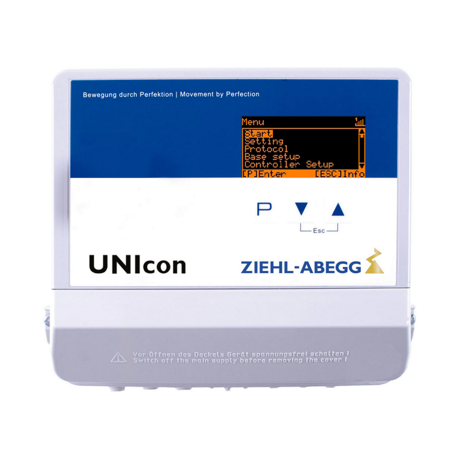
ZIEHL-ABEGG UNIcon MODBUS Master Operating Instructions Manual (83 pages)
Control module with integrated pressure sensor e.g. for central extraction systems
Brand:
ZIEHL-ABEGG
| Category:
Control Unit
| Size: 2 MB
Table of Contents
Table of Contents
2
1 General Notes
5
Structure of the Operating Instructions
5
Target Group
5
Exclusion of Liability
5
Copyright
5
2 Safety Instructions
5
Explanations of Symbols
6
Product Safety
6
Requirements Placed on the Personnel / Due Diligence
6
Start-Up and During Operation
6
Work on the Device
7
Modifications / Interventions in the Device
7
Operator's Obligation of Diligence
7
Employment of External Personnel
7
3 Product Overview
8
Operational Area
8
Transport
8
Storage
8
Disposal / Recycling
8
4 Mounting
8
General Notes
8
Connection Pressure Measuring Tube
9
Outdoor Installation
9
Installation Location for Agriculture
9
Temperature Influences During Commissioning
9
5 Electrical Installation
9
Safety Precautions
9
EMC-Compatible Installation of Control Lines
10
Mains Connection
10
Signal Input or Sensor Connection (E2)
10
Control Outputs 0 - 10 V (A1, A2)
11
Voltage Supply for External Devices (+24V, GND)
11
Digital Inputs (D1, D2)
11
Relay Outputs (K1, K2)
12
RS-485 Interfaces for MODBUS RTU
12
Addressing Member MODBUS Master Interface
13
USB-Interface
15
Potential at Control Voltage Connections
15
6 Select Operation Mode
15
Mode and Signal Input
15
Operation with a Second Control Circuit
16
External Setpoint / External Speed Setting in Manual Operation
18
7 Start-Up
18
Prerequisites for Commissioning
18
8 Controls and Menu
21
Multipurpose LC Display and Keyboard
21
Menu Operation
22
Example for Programming Mode 4.01 in "Base Setup
22
Menu Structure
23
Overview Menu Groups
24
9 Programming
25
Pressure Control Airconditioning 4.01
25
Base Setup 4.01
25
Setting for Operation Modes 4.01
26
Air Volume Control
28
Base Setup
28
Settings for Operation Modes 5.01
29
Menu Group Start
30
Menu Group Info
31
Controller Setup
32
PIN Protection Activate, PIN 0010
32
PIN Protection Activate, PIN 1234
33
Save User Settings Restore with PIN 9090
33
Sensor Alarm on / off
33
Limit
34
Minimum Speed Cut off
34
Reverse Action of the Control Function
35
Controller Configuration
35
Group Control
37
Variant "0": One Controlled Group and up to Three Switched Groups
38
Version "1": Two Controlled Groups
40
Display Text for External Message
40
Offset Control Signal
41
Selection Amplifier (Comparator) Control Circuit 1 or 2 at Output A1
41
Data on the Total Control Deviation
42
IO Setup
42
Analog Outputs "A1"/ "A2
42
Digital Inputs "D1" / "D2
44
Menu Overview
44
Enable ON/OFF Function | 1D
45
(Operation with One Control Cicuit)
46
External Message, Function | 2D
46
Limit on / OFF, Function | 3D
46
Switch over Input "E1" / "E2", Function | 4D
46
Output Control Circuit 2 Additional to "A2" on "A1", Function
47
Set 1/2 or Setpoint 1/2, Function
47
Automatic Control / Speed Manual Function (Mode )
48
Intern / Extern Function | 6D
48
Function | 8D
49
Reverse Action of Control Function
49
Switch over Setpoint 1/2 for Control Circuit 2 | 9D
49
Setting Max. Speed on / off Function
50
Switch over Setpoint 1/2 and Pband 1/ 2 for Control Circuit 1
50
Switch over Setpoint 1/2 and Pband 1/2 for Control Circuit 2
51
Timer Function Overwrite
51
Configuration of Analog Inputs "E1"And "E2
52
Signal Adaption E1 and E2
52
E1" / "E2" Bus Mode
54
Inverting Analog Inputs "E1" / "E2
54
Function and Inverting for Relay Outputs "K1" and "K2
55
COM2 Function
56
Limits
56
Limit Indication Depending on Modulation
56
Limit Indication Depending on Setting or Sensor Signal
57
Timer
60
Timerfunction
60
Setting of Time and Date
61
Automatic Summer Time
62
Enter Switching Times
62
Inverting Timer Function
63
Adjustment of the Real Time Clock
64
Overwrite Timer Function
64
MODBUS Slave
64
MODBUS Master
65
Automatic Addressing
65
Manual Addressing
66
Member MOBUS Master
67
10 Menu Tables
68
Menues of Operating Modes
68
Possible Allocation of the Ios, Pins
72
11 Diagnostics Menu
75
12 Protocol
76
Display and Query of Events and Malfunctions
76
Messages and Trouble Shooting
77
13 Enclosure
80
Technical Data
80
Connection Diagram
81
Dimensions [MM]
81
Index
82
Manufacturer Reference
83
Service Information
83
Advertisement
Advertisement
Related Products
ZIEHL-ABEGG UNIcon MODBUS Master CXE/AV
ZIEHL-ABEGG UNIcon MODBUS Master CXE/AVE
ZIEHL-ABEGG UNIcon CPG AVC Series
ZIEHL-ABEGG Unicon CXE/AVCE
ZIEHL-ABEGG Unicon CXE/AVC
ZIEHL-ABEGG UNIcon
ZIEHL-ABEGG UNIcon Series
ZIEHL-ABEGG UNIcon CTE/AH-L
ZIEHL-ABEGG Ucontrol PXDM Series
ZIEHL-ABEGG ALARMcon UTE-32A-L
ZIEHL-ABEGG Categories
Fan
Engine
Control Unit
DC Drives
Controller
More ZIEHL-ABEGG Manuals
Login
Sign In
OR
Sign in with Facebook
Sign in with Google
Upload manual
Upload from disk
Upload from URL