Sign In
Upload
Download
Table of Contents
Contents
Add to my manuals
Delete from my manuals
Share
URL of this page:
HTML Link:
Bookmark this page
Add
Manual will be automatically added to "My Manuals"
Print this page
×
Bookmark added
×
Added to my manuals
Manuals
Brands
Leuze electronic Manuals
Security Sensors
SD4T 14
Connecting and operating instructions
Leuze electronic SD4T 14 Connecting And Operating Instructions
Safety light curtain
Hide thumbs
1
2
Table Of Contents
3
4
5
6
7
8
9
10
11
12
13
14
15
16
17
18
19
20
21
22
23
24
25
26
27
28
29
30
31
32
33
34
35
36
37
38
39
40
41
42
43
44
45
46
47
48
49
50
51
52
53
54
55
56
57
58
59
60
61
62
63
64
65
66
67
68
69
70
71
72
73
page
of
73
Go
/
73
Contents
Table of Contents
Troubleshooting
Bookmarks
Table of Contents
Table of Contents
1 General
Certifications
Symbols and Terms
SOLID-4 Selection
2 Safety
Approved Purpose and Foreseeable Improper Operation
Proper Use
Foreseeable Misuse
Competent Personnel
Responsibility for Safety
Exemption of Liability
SOLID-4 Safety Light Curtains with a Resolution of 14 MM to 40 MM
SOLID-4 Safety Light Curtains with a Resolution of ≥ 40 MM
Additional Safety Instructions for Access Guarding with SOLID-4
3 System Setup and Possible Uses
The Opto-Electronic Protective Device
Cascading Option
4 Functions
Selectable Functions of the SD4T Transmitter
Transmission Channel
Selectable Functions of the SD4R-E Receiver
Start/Restart Interlock (RES)
Contactor Monitoring (EDM)
Functions of Receiver SD4R
Diagnostics Function: Dirt and Error Signal Output
Test Input
5 Display Elements
SD4T Transmitter Status Displays
SD4R-E Receiver Status Displays
7-Segment Displays
LED Displays
SD4R Receiver Status Displays
7-Segment Display
LED Displays
6 Installation
Calculating Minimum Distances
Safety Distance for Point of Operation Guarding
Safety Distance for Danger Zone Guarding
Safety Distance and Beam Heights for Safety Light Curtains as Access Guarding
Minimum Distance from Reflective Surfaces
Mounting Notes
Mechanical Mounting
Mounting Types
Standard Mounting
Option: Mounting with Swiveling Brackets
Option: Side Mounting
7 Electrical Connection
M12 Coupling
Transmitter
Receiver SD4R-E
Receiver SD4R
Connection Examples
Connection Example for Transmission Channel 1(TC1)
Connection Example for Transmission Channel 2 (TC2)
SOLID-4 Connection Example with Downstream Relay Module, MSI-RM2
Connection Example of SOLID-4 with Downstream MSI-SR4 Safety Interface Device
8 Startup
Switching on
Display Sequence with SD4T Transmitter
Display Sequence with SD4R-E Receiver
Display Sequence on Receiver SD4R
Aligning Transmitter and Receiver
Optimizing Alignment by Turning And/Or Tilting the Transmitter and Receiver
9 Testing
Testing before First Startup
Regular Tests
Daily Testing with the Test Rod
Cleaning the Front Screens
10 Troubleshooting
What Do I Do if an Error Occurs
Diagnostics
SD4T Transmitter Diagnostic
SD4R-E Receiver Diagnostics
Autoreset
11 Technical Data
General Data
Protective Field Data
Safety-Relevant Technical Data
General System Data
SD4T Transmitter Signal Input
SD4R-E Receiver Signal Inputs/Outputs
Safety-Related Transistor Outputs
Safety Light Curtain/Host Dimensions, Weights, Response Times
Safety Light Curtain/Guest Dimensions, Weights, Response Times
Number of Beams for Host / Guest Devices
Bracket Dimensions
12 Appendix
SOLID-4 Scope of Delivery
SOLID-4 Ordering Information
SOLID-4E Host Ordering Information
SOLID-4 Guest Ordering Information
SOLID-4 Accessories Ordering Information
Checklists
Checklist for Point of Operation Guarding
Checklist for Danger Zone Guarding
Checklist for Access Guarding
EC Declaration of Conformity
Advertisement
Quick Links
1
Diagnostics
2
What Do I Do if an Error Occurs
Download this manual
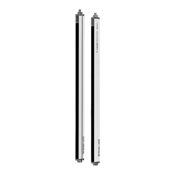
SOLID-4
Safety Light Curtain
C O N N E C T I N G A N D O P E R A T I N G I N S T R U C T I O N S
O r i g i n a l I n s t r u c t i o n s
Table of
Contents
Previous
Page
Next
Page
1
2
3
4
5
Advertisement
Table of Contents
Need help?
Do you have a question about the SD4T 14 and is the answer not in the manual?
Ask a question
Questions and answers
Related Manuals for Leuze electronic SD4T 14
Security Sensors Leuze electronic SOLID-2 Series Connecting And Operating Instructions
Safety light curtain (58 pages)
Security Sensors Leuze electronic SOLID-4 Connecting And Operating Instructions
Safety light curtain (73 pages)
Security Sensors Leuze electronic RSL 430 Original Operating Instructions
Safety laser scanner (127 pages)
Security Sensors Leuze electronic MLD 300 Original Operating Instructions
Multiple light beam safety devices (118 pages)
Security Sensors Leuze electronic MLC 520 Operating Instructions Manual
Safety light curtains (65 pages)
Security Sensors Leuze electronic CU411-RS4 Supplement To Original Operating Instructions
Rs4 compability set for rsl 410 and 420 (58 pages)
Security Sensors Leuze electronic MLC 500 Original Operating Instructions
Safety light curtains (69 pages)
Security Sensors Leuze electronic MLC 500 Series Safe Implementation And Operation
Safety light curtains (60 pages)
Security Sensors Leuze electronic MLC 300 Series Manual
Ip protective tube for mlc safety light curtains (31 pages)
Security Sensors Leuze electronic CML 720i Ex Operating Instructions Manual
Measuring light curtain (141 pages)
Security Sensors Leuze electronic ERS200-M0C3-M20-HLR Operating Instructions Manual
Safety command devices (43 pages)
Security Sensors Leuze electronic CRT448 Quick Start Manual
Color sensors (6 pages)
Security Sensors Leuze electronic OPSL 775 Manual
Laser edge detector (12 pages)
Security Sensors Leuze electronic MLC 510 AS-i Host/Guest Safe Implementation And Operation
Safety light curtains (59 pages)
This manual is also suitable for:
Solid-4
Sd4r 20
Sd4t 30
Sd4t 40
Sd4r 30
Sd4t 20
...
Show all
Sd4r 14
Sd4r 40
Sd4t 90
Sd4r 90
Table of Contents
Print
Rename the bookmark
Delete bookmark?
Delete from my manuals?
Login
Sign In
OR
Sign in with Facebook
Sign in with Google
Upload manual
Upload from disk
Upload from URL


Need help?
Do you have a question about the SD4T 14 and is the answer not in the manual?
Questions and answers