Table of Contents
Advertisement
KINNEY
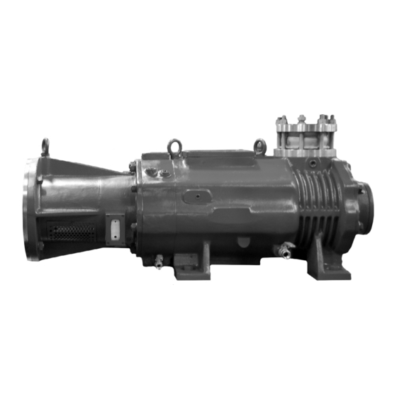
Dry Vacuum Pumps
Models
SDV-120
INSTALLATION
OPERATION
MAINTENANCE
REPAIR
MANUAL
WARNING
DO NOT OPERATE
BEFORE READING MANUAL
SDV™ SERIES
®
SDV-200
SDV-320
SDV-430
SDV-800
Tuthill Vacuum & Blower Systems
4840 West Kearney Street
Springfield, Missouri USA 65803-8702
o 417.865.8715 800.825.6937 f 417.865.2950
www.tuthillvacuumblower.com
Advertisement
Table of Contents

Related Manuals for Tuthill KINNEY SDV SDV-120


Summary of Contents for Tuthill KINNEY SDV SDV-120
- Page 1 Dry Vacuum Pumps Models SDV-120 SDV-200 SDV-320 SDV-430 SDV-800 INSTALLATION OPERATION MAINTENANCE REPAIR MANUAL WARNING DO NOT OPERATE BEFORE READING MANUAL Tuthill Vacuum & Blower Systems 4840 West Kearney Street Springfield, Missouri USA 65803-8702 o 417.865.8715 800.825.6937 f 417.865.2950 www.tuthillvacuumblower.com...
- Page 2 WARNING CAUTION DO NOT VALVE OR RESTRICT PUMP DISCHARGE OPENING. USE OIL MIST ELIMINATOR WHEN OPERATING PUMP, ENSURE ADEQUATE VENTILATION WHEN DISCHARGING INDOORS DO NOT OPERATE REFER TO MANUAL SAFETY INSTRUCTIONS. WITHOUT BELT GUARD NOTICE The above safety instruction tags were permanently affixed to your pump prior to shipment. Do not remove, paint over or obscure in any manner.
-
Page 3: Table Of Contents
TABLE OF CONTENTS SECTION PAGE INTRODUCTION PRINCIPAL OF OPERATION CONSTRUCTION TIMING GEAR BEARINGS OIL LEVEL GAUGE OIL LEVEL SENSOR MATERIALS OF CONSTRUCTION SPECIFICATIONS TABLE PIPING DIAGRAM FRESH WATER-COOLING AIR-WATER RADIATOR PURGES STEAM FLUSHING STEAM FLUSHING METHOD (AFTER PUMP OPERATION) HANDLING PROCEDURE ASSEMBLY OF PIPING PIPING WORK OPERATION... -
Page 4: Introduction
INTRODUCTION CONGRATULATIONS on your purchase of a new KINNEY® SDV™ Dry Vacuum Pump from Tuthill Vacuum & Blower Systems. Please examine the pump for shipping damage, and if any damage is found, report it immediately to the carrier. If the pump is to be installed at a later date make sure it is stored in a clean, dry location and rotated regularly. -
Page 5: Oil Level Gauge
OIL LEVEL GAUGE An oil level gauge (sight glass type) is located on the front end cover. Oil should be filled to the top level of the Red Mark, or OL Mark. Oil Levels are indicated as below for the pumps manufactured after October 2005: Original Line (Oil should be filled up to this line initially) Running High (During the Operation) ---- In this case, pump should be checked. -
Page 6: Specifications Table
SPECIFICATIONS TABLE SDV-120 SDV-200 SDV-320 SDV-430 SDV-800 SDV-1500 SDV-2700 MODEL 50 Hz 60 Hz 50 Hz 60 Hz 50 Hz 60 Hz 50 Hz 60 Hz 50 Hz 60 Hz 50 Hz 60 Hz 50 Hz 60 Hz Nominal 1324 1588 Displacement m³/hr... -
Page 7: Piping Diagram
PIPING DIAGRAM The vacuum pump casing and the front end plate have an integrated cooling water jacket. The SDV series pumps can be configured with two different types of cooling systems, Fresh Water Cooling and Circulating Cooling. FRESH WATER-COOLING The fresh water cooling system consists of a “once through” cooling water circuit. A flow indicator, flow switch on the cooling water supply line and temperature guage (or switch) at the cooling water discharge line should be installed to monitor the adequacy of the colling water flow and the cooling water discharge temperature. -
Page 8: Air-Water Radiator
AIR-WATER RADIATOR This system is an air-cooled version with a cooling water total recovery system. A centrifugal pump circulates the cooling water from the SDV vacuum pump to a radiator-fan unit. A flow indicator, flow switch on the cooling water supply line and temperature guage (or switch) at the cooling water discharge line should be installed to monitor the adequacy of the colling water flow and the cooling water discharge temperature. -
Page 9: Purges
PURGES COOLING PURGE — Cooling Purge is to cool the inside of the casing and the screws. During the operation of the pump, the process gas introduced into the casing through the suction nozzle is compressed by the rotation of the screws and transferred to the discharge side. -
Page 10: Steam Flushing
Stop (Cleaning) Purge: Upon completion of process pumping operation, close the inlet process isolation valve and start supplying the purge gas to the pump while the pump is continuously operating for 20 to 30 mintes to remove residual process gas from the pump internals. -
Page 11: Handling Procedure
• Flow rates listed are Minimum. • FLUSHING PURGE should last for 30 minutes with the pump suction valve closed, after process operation is ended. • All PURGE work except for flushing should be done at the same time as the process starts up. •... -
Page 12: Operation
supply line can by employed by installing piping between the cooling liquid discharge nozzle at the pump Casing to the cooling liquid supply connection nozzle on the silencer or the after cooler. Cooling medium supply piping should include the instruments listed below: * If a Water Jacket type Silencer or After Cooler is installed, this Silencer / After Cooler also requires Cooling water piping. -
Page 13: Pump Shutdown
PUMP SHUTDOWN Prior to disconnection of the motor power, ensure to close the process inlet isolation valve. Where the process gas or vapor is in corrosive or hazardous nature, introduce inert gas, such as Nitrogen or Argon, into the pump inlet for 20 to 30 minutes to purge out the residual process gas or vapor from the pump internals prior to disconnecting the motor power. -
Page 14: Dry Vacuum Pump Maintenance & Inspection Schedule
MONTHLY Check the oil color: If the oil color is too dark, replace the oil. Check oil level: If the oil level drops in a short period of time, check the integrity of mechanical seals. Check grease. QUARTERLY Check the cooling liquid flow and discharge cooling liquid color. May require periodic cleaning of the cooling jackets and water piping. -
Page 15: Disassembly And Reassembly
DISASSEMBLY: PRECAUTIONS AND PROCEDURE Notes for the steps for the models after October 2005: This revision includes steps for the SDV pump models manufactured after October 2005. The additional steps are noted by superscripted “new” on the right hand side of the step numbers, for example, (54) “NEW”. -
Page 16: Reassembly Procedure
26. Remove set screws from Mechanical Seal Rotor (A) and pull out the Mechanical Seal Rotor (A) 27. Push out Screws 28. Remove bolts (M10) and separate the FEP from the pump casing 29. Press out Lip Seals, Lantern Rings and Mechanical Seal Stators (A) 30. - Page 17 22. Add or remove shims if required to meet the clearance specification per the Table 7 Screw Clearance Table. ASSEMBLY OF FEP/SCREWS/SHAFT TO CASING 23. Separate the REP from the Screws/Shafts and place the assembled FEP/Screws/Shaft horizontally 24. Place casing on the workbench. 25.
- Page 18 SCREW CLEARANCE TABLE SCREW CLEARANCE TABLE Shown in inches and millimeters. MODEL “D” CLEARANCES “E” CLEARANCES SDV-120 0.0039 - 0.0047 / 0.10 - 0.12 0.0016 - 0.0024 / 0.01 - 0.06 0.10 - 0.12 0.05 - 0.07 SDV-200 0.0039 - 0.0047 / 0.0020 - 0.0028 / SDV-320 0.0039 - 0.0059 /...
-
Page 19: Vacuum System Checklist
VACUUM SYSTEM CHECKLIST CHECK POINT CHECK Opening Cooling water supply valve. Is flow correct? Close vacuum suction line. Open Discharge line. Before Operation Check lubricant color and level. Is it acceptable? Check Belt Tension (for V-belt type only) ... -
Page 20: Exploded View Drawings And Parts Lists
SDV 120-200 EXPLODED VIEW DRAWING 68 36 NOTES:... - Page 21 SDV 120-200 PARTS LIST ITEM ITEM DESCRIPTION DESCRIPTION MECHANICAL SEAL STATOR (B) CASING MECHANICAL SEAL ROTOR (B) FRONT END PLATE SEAL ADAPTER HOUSING COVER REAR END PLATE BLIND PLATE (A) FRONT END COVER BLIND PLATE (B) DRIVER SHAFT (A) BLIND PLATE (C) DRIVEN SHAFT (B) BLIND PLATE (D) SCREW...
- Page 22 NEW SDV 120 EXPLODED VIEW DRAWING 17 63 15-1 NOTES:...
- Page 23 NEW SDV 120 PARTS LIST ITEM ITEM DESCRIPTION DESCRIPTION CASING SEAL ADAPTER HOUSING FRONT END PLATE MECHANICAL SEAL STATOR (B) REAR END PLATE MECHANICAL SEAL ROTOR (B) FRONT END COVER SEAL ADAPTER HOUSING COVER DRIVER SHAFT (A) BLIND PLATE (A) DRIVEN SHAFT (B) BLIND PLATE (B) SCREW...
- Page 24 NEW SDV 200 EXPLODED VIEW DRAWING 20 16 15-1 NOTES:...
- Page 25 NEW SDV 200 PARTS LIST ITEM ITEM DESCRIPTION DESCRIPTION CASING MECH SEAL ROTATOR FRONT END PLATE SEAL ADAP HOUSING COVER REAR END PLATE BLIND PLATE (A) FRONT END COVER BLIND PLATE (B) DRIVER SHAFT (A) BLIND PLATE (C) DRIVEN SHAFT (B) BLIND PLATE (D) SCREW LOCK NUT...
- Page 26 SDV 320 EXPLODED VIEW DRAWING NOTES:...
- Page 27 SDV 320 PARTS LIST ITEM ITEM DESCRIPTION DESCRIPTION CASING SEAL ADAPTER HOUSING FRONT END PLATE MECHANICAL SEAL STATOR (B) REAR END PLATE MECHANICAL SEAL ROTOR (B) FRONT END COVER SEAL ADAPTER HOUSING COVER DRIVER SHAFT (A) BLIND PLATE (A) DRIVEN SHAFT (B) BLIND PLATE (B) SCREW BLIND PLATE (C)
- Page 28 NEW SDV 320 EXPLODED VIEW DRAWING NOTES:...
- Page 29 NEW SDV 320 PARTS LIST ITEM ITEM DESCRIPTION DESCRIPTION CASING SEAL ADAPTER HOUSING COVER FRONT END PLATE BLIND PLATE (A) REAR END PLATE BLIND PLATE (B) FRONT END COVER BLIND PLATE (C) DRIVER SHAFT (A) BLIND PLATE (D) DRIVEN SHAFT (B) SCREW SIGHT GLASS ASS’Y LOCK NUT...
- Page 30 SDV 430 EXPLODED VIEW DRAWING NOTES:...
- Page 31 SDV 430 PARTS LIST ITEM ITEM DESCRIPTION DESCRIPTION CASING SEAL ADAPTER HOUSING FRONT END PLATE MECHANICAL SEAL STATOR (B) REAR END PLATE MECHANICAL SEAL ROTOR (B) FRONT END COVER SEAL ADAPTER HOUSING COVER DRIVER SHAFT (A) BLIND PLATE (A) DRIVEN SHAFT (B) BLIND PLATE (B) SCREW BLIND PLATE (C)
- Page 32 NEW SDV 430 EXPLODED VIEW DRAWING 15-1 NOTES:...
- Page 33 NEW SDV 430 PARTS LIST ITEM ITEM DESCRIPTION DESCRIPTION CASING SEAL ADAP HOUSING COVER FRONT END PLATE BLIND PLATE (A) REAR END PLATE BLIND PLATE (B) FRONT END COVER BLIND PLATE (C) DRIVER SHAFT (A) BLIND PLATE (D) DRIVEN SHAFT (B) SCREW SIGHT GLASS ASS’Y LOCK NUT...
- Page 34 SDV 800 EXPLODED VIEW DRAWING NOTES:...
- Page 35 SDV 800 PARTS LIST ITEM ITEM DESCRIPTION DESCRIPTION CASING SEAL ADAPTER HOUSING FRONT END PLATE MECHANICAL SEAL STATOR (B) REAR END PLATE MECHANICAL SEAL ROTOR (B) FRONT END COVER SEAL ADAPTER HOUSING COVER DRIVER SHAFT (A) BLIND PLATE (A) DRIVEN SHAFT (B) BLIND PLATE (B) SCREW BLIND PLATE (C)
- Page 36 NEW SDV 800 EXPLODED VIEW DRAWING 15-1 NOTES:...
- Page 37 NEW SDV 800 PARTS LIST ITEM ITEM DESCRIPTION DESCRIPTION CASING SEAL ADAP HOUSING COVER FRONT END PLATE BLIND PLATE (A) REAR END PLATE BLIND PLATE (B) FRONT END COVER BLIND PLATE (C) DRIVER SHAFT (A) BLIND PLATE (D) DRIVEN SHAFT (B) SCREW SIGHT GLASS ASS’Y LOCK NUT...
- Page 38 SDV 1500 EXPLODED VIEW DRAWING NOTES:...
- Page 39 SDV 1500 PARTS LIST ITEM ITEM DESCRIPTION DESCRIPTION CASING GEAR STOPPER FRONT END PLATE SEAL ADAPTER HOUSING REAR END PLATE MECHANICAL SEAL STATOR FRONT END COVER MECH SEAL ROTOR DRIVER SHAFT (A) DUST COVER DRIVEN SHAFT (B) BLIND PLATE (A) SCREW BLIND PLATE (B) LOCKNUT...
- Page 40 SDV 2700 EXPLODED VIEW DRAWING NOTES:...
- Page 41 SDV 2700 PARTS LIST ITEM ITEM DESCRIPTION DESCRIPTION CASING POWER LOCK FRONT END PLATE GEAR STOPPER REAR END PLATE SEAL ADAPTER HOUSING FRONT END COVER MECHANICAL SEAL STATOR (B) DRIVER SHAFT (A) MECHANICAL SEAL ROTOR (B) DRIVEN SHAFT (B) DUST COVER SCREW BLIND PLATE (A) LOCKNUT...
-
Page 42: Warranty - Vacuum Products
WARRANTY – VACUUM PRODUCTS Subject to the terms and conditions hereinafter set forth and set forth in General Terms of Sale, Tuthill Vacuum & Blower Systems (the seller) warrants products and parts of its manufacture, when shipped, and its work (including installation and start-up) when performed, will be of good quality and will be free from defects in material and workmanship. - Page 43 IMPORTANT All KINNEY vacuum pumps manufactured by Tuthill Vacuum & Blower Systems are date coded at time of shipment. In order to ® assure you of the full benefits of the product warranty, please complete, tear out and return the product registration card below, or you can visit our product registration web page at: http://www.tuthillvacuumblower.com/index.cfm/contact-us/product-registration/...
- Page 44 NECESSARY IF MAILED IN THE UNITED STATES BUSINESS REPLY MAIL FIRST-CLASS MAIL PERMIT NO. 2912 SPRINGFIELD MO POSTAGE WILL BE PAID BY ADDRESSEE ATTN. CUSTOMER SERVICE – VACUUM PRODUCTS TUTHILL VACUUM & BLOWER SYSTEMS PO BOX 2877 SPRINGFIELD MO 65890-2150...
Need help?
Do you have a question about the KINNEY SDV SDV-120 and is the answer not in the manual?
Questions and answers