Table of Contents
Advertisement
Quick Links
LR5092-20
DATA COLLECTOR
Be sure to read this manual before using the instrument.
When using the instrument for the
first time
Part Names/Functions
Preparation for Use
Mar. 2019 Revised edition 3
LR5092B980-03 19-03H
Troubleshooting
p.10
Troubleshooting
p.15
Error Display
Instruction Manual
p.3
p.128
p.130
EN
Advertisement
Table of Contents

Related Manuals for Hioki LR5092-20


Summary of Contents for Hioki LR5092-20
- Page 1 LR5092-20 Instruction Manual DATA COLLECTOR Be sure to read this manual before using the instrument. p.3 When using the instrument for the Troubleshooting first time Part Names/Functions p.10 Troubleshooting p.128 Preparation for Use p.15 Error Display ...
-
Page 3: Table Of Contents
Contents Contents Introduction ................1 Verifying Package Contents............2 Safety Information..............3 Operating Precautions.............4 Preparation for Use to Data Analysis ........6 Chapter 1 Overview ___________________________________ 9 Product Overview and Features .......9 Part Names/Functions ..........10 Basic Button Operations and Display Organization .............11 Chapter 2 Preparation for Use _________________________ 15 Installing (or Replacing) the Battery ......15 ... - Page 4 Contents Chapter 4 Collecting and Browsing Data ________________ 31 Collecting Recorded Data of Logger ....31 One-touch Collection (Collecting Data Easily by Just Pressing COLLECT Button) ..........31 Selecting the Data Save Destination and Then Performing Collection ............35 Chapter 5...
- Page 5 Contents Chapter 7 Using the LR5000 Utility Program _____________ 65 Installing the PC Application Program ....65 LR5000 Utility Program Screens........... 68 Setting the Collector from the LR5000 Utility Program ..............71 Saving Setting Data from the LR5000 Utility Program to the SD Memory Card ......82 Automatically Importing (Saving) Recorded Data ...
- Page 6 Contents Chapter 9 Maintenance and Service ___________________ 127 Requesting Repairs ............. 127 When the logger will not be used for long time ....127 Lifespan of Backup Battery ..........127 Cleaning ..............127 Troubleshooting ........... 128 Error Display ............130 Disposing of the Logger ........
-
Page 7: Contents
Introduction Introduction Thank you for purchasing the HIOKI "Model LR5092-20 Data Collector." To obtain maximum performance from the instrument, please read this manual first, and keep it handy for future reference. Registered Trade Marks •Microsoft, Windows are registered trademarks of Microsoft Corporation in the United States and/or other countries. -
Page 8: Verifying Package Contents
When you receive the instrument, inspect it carefully to ensure that no damage occurred during shipping. In particular, check the accessories, panel switches, and connectors. If damage is evident, or if it fails to operate according to the specifica- tions, contact your dealer or Hioki representative. Quantities in parentheses ( ). Accessories... -
Page 9: Safety Information
Safety Information Safety Information This manual contains information and warnings essential for safe operation of the instrument and for maintaining it in safe operating condition. Before using it, be sure to carefully read the following safety precautions. This logger is designed to comply with IEC 61010 Safety Standards, and has been thoroughly tested for safety prior to shipment. -
Page 10: Operating Precautions
Operating Precautions Danger Levels The following symbols in this manual indicate the relative importance of cautions and warnings. Indicates that incorrect operation presents an extreme hazard that could result in serious injury or death to the user. Indicates that incorrect operation presents a significant hazard that could result in serious injury or death to the user. - Page 11 Never use abrasives or sol- vent cleaners. • Hioki shall not be held liable for any problems with a computer system that arises from the use of this CD, or for any problem related to the purchase of a Hioki product.
-
Page 12: Preparation For Use To Data Analysis
Collect the data of all loggers, send the data to a computer, and ana- lyze and store the data on the computer. Required Items: Quantities in parentheses ( ). LR5092-20 (1) LR6 alkaline battery (2) Computer (1) LR5000 Utility Program CD ... - Page 13 Preparation for Use to Data Analysis Turn on the power. "2.3" (p.19) See: Perform an inspection before use. "2.4" (p.20) See: Push Connect a logger to the collector and collect the recorded data. "4.1" (p.31) See: Verify the collected data. "4.1"...
- Page 14 Preparation for Use to Data Analysis...
-
Page 15: Chapter 1 Overview
1.1 Product Overview and Features Chapter 1 Overview 1.1 Product Overview and Features This instrument is a compact data collector that can set the measurement condi- tions and import the recording data of the LR5000-series loggers. This is useful when you are using multiple loggers. SD Memory Card Support You can easily transfer data to Large Display Shows Recorded... -
Page 16: Part Names/Functions
1.2 Part Names/Functions 1.2 Part Names/Functions Front Back Display (p.11) USB Port (p.71) The backlight turns off if no operation is per- Connect a computer using the supplied formed for approximately 30 seconds. USB cable. The backlight turns on again when a button is pressed or communication is performed. -
Page 17: Basic Button Operations And Display Orga- Nization
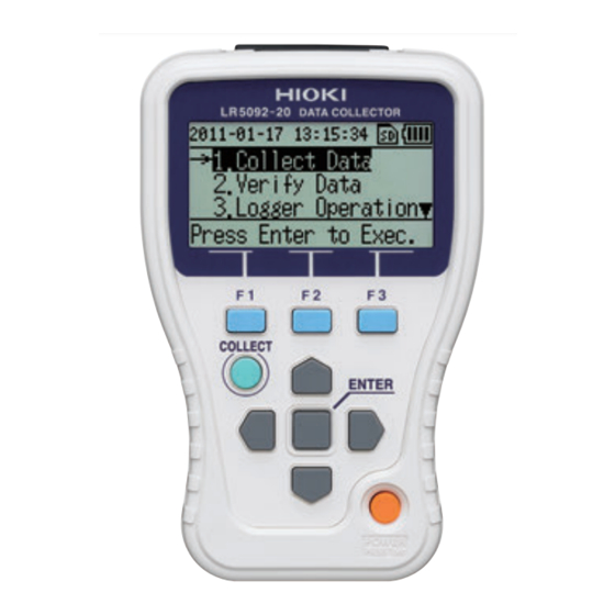
1.3 Basic Button Operations and Display Organization Display Current Date SD Memory Card Indicator Indicates the set date that is cur- Lit when an SD memory card is inserted. rently set. "2.2 Inserting an SD Card (When Necessary)" See: "Clock Setting" (p.59) See: Battery Status Indicator (p.15) Indicates the battery charge status. - Page 18 1.3 Basic Button Operations and Display Organization Display Organization Startup Display (Top Display) This display is shown for several seconds. Software version information Memory Usage Status Display This display appears when Startup Dis- is set to play Memory Status Use the button to select the next dis- play to show.
- Page 19 1.3 Basic Button Operations and Display Organization Data Collection display Shows the data collection operation menu items. Set the collection destination and collection meth- od for data. "Selecting the Data Save Destination and See: Then Performing Collection" (p.35) Data Verification display Shows a list of the recorded data that was col- lected.
- Page 20 1.3 Basic Button Operations and Display Organization SD Card display Shows the data management menu items. The following operations are possible. • Showing a list of data in an SD memory card (p.39) • Moving data from the collector memory to an SD memory card (p.42) •...
-
Page 21: Chapter 2 Preparation For Use
2.1 Installing (or Replacing) the Battery Chapter 2 Preparation for Use 2.1 Installing (or Replacing) the Battery • After replacing the batteries, replace the cover before using the instrument. • Do not mix old and new batteries, or different types of batteries. Also, be careful to observe battery polarity during installation. - Page 22 2.1 Installing (or Replacing) the Battery •The data saved to the collector and time settings are retained even when the batteries are depleted or replaced. •When the collector is connected to a computer via a USB cable, the battery power is not consumed because power is supplied to the collector from the computer.
-
Page 23: Inserting An Sd Card (When Necessary)
If this happens, purchase a new SD memory card. • Hioki will not compensate for the loss of any data stored in an SD memory card regardless of circumstances or cause of the failure or damage that resulted in the loss. -
Page 24: Sd Memory Cards For Which Operation Is Guaranteed
(The SD memory card is ejected.) Pull the SD memory card straight out. SD Memory Card Slot SD Memory Cards for which Operation is Guaranteed HIOKI Z4001 SD Memory Card 2GB We strongly recommend using Hioki optional SD memory cards. -
Page 25: Turning The Power On/Off
2.3 Turning the Power On/Off 2.3 Turning the Power On/Off Each press of the POWER button (long press for approximately 1 second) turns the power on/off. (The power is turned on when the device is connected to the PC via a USB cable. -
Page 26: Inspection Before Use
2.4 Inspection Before Use 2.4 Inspection Before Use Inspect the following items before use. Damaged Is any damage to the Data Request repair. Collector? "Requesting Repairs" (p.127) See: No damage Logger communication may not be possible. Clean the infrared port. Damaged Is the infrared port damaged "9.1 Cleaning"... -
Page 27: Settings (When Necessary)
3.1 Making Settings with the Collector Settings Chapter 3 (When Necessary) You can set the measurement conditions of a logger with the collector, and then send the settings to the logger. (This feature is convenient when you want to set the same settings on multiple loggers.) It is also possible to receive the settings of a logger, and then send those settings to a dif- ferent logger. -
Page 28: Settings List
3.2 Settings List 3.2 Settings List The following is a list of all settings. LR5000 Util- Setting Item Setting Description Collector ity Program Logger Type (Collector) Model Select the logger model. (p.24) (p.75) (LR5000 Utility Program) Rec Interval Select the recording interval. (p.24) (p.76) Rec start time... - Page 29 3.2 Settings List LR5000 Util- Setting Item Setting Description Collector ity Program If this is set to ON (enabled), the logger will run in power saving mode. (The dis- play turns off if no operation is per- Power Saving (Collector) formed for approximately 30 seconds.) Power save setting (p.24)
- Page 30 3.2 Settings List Settings and Options (Collector) The following shows the options that can be selected for each setting that can be made with the collector. LR5001 / LR5011 / LR5021 / LR5031 / LR5041 / (Initial Setting) Logger Type LR5042 / LR5043 / LR5051 / LR5061 / 2 / 5 / 10 / 15 / 20 / 30 sec.
- Page 31 3.2 Settings List Recording Start/Stop Method Rec start time Select the recording start method. When [Scheduled time] is selected, specify the start date and time. Setting Item Setting Description Button operation Starts recording by pressing the button on the logger. (Initial Setting) Starts recording from specified time after settings sent to the Data Start After Sent...
-
Page 32: Sending Measurement Condition Settings To Logger
3.3 Sending Measurement Condition Settings to Logger 3.3 Sending Measurement Condition Settings to Logger Connect a logger to the collector, and then send the measurement conditions to the logger. Required Items: Logger to which you want to send the settings Show the top display of the collector. -
Page 33: Receiving Measurement Condition Settings From Logger
3.4 Receiving Measurement Condition Settings from Logger 3.4 Receiving Measurement Condition Settings from Logger Connect a logger to the collector, and then receive the measurement conditions from the logger. Required Items: Logger from which you want to receive the settings Show the top display of the collector. -
Page 34: Verifying Recording/Setting Status Of Logger
3.5 Verifying Recording/Setting Status of Logger Verifying Recording/Setting Status of Logger You can verify the current recording/setting status of the logger. Required Items: Logger for which you want to verify the recording/setting status Show the top display of the collector. (To return to the top display from another dis- [Back] [Cancel]... -
Page 35: Starting And Stopping Recording On Logger
3.6 Starting and Stopping Recording on Logger 3.6 Starting and Stopping Recording on Logger The collector can control the starting and stopping of recording on the logger. Required Items: The logger for which you want to start/stop recording Show the top display of the collector. (To return to the top display from another dis- [Back] [Cancel]... - Page 36 3.6 Starting and Stopping Recording on Logger...
-
Page 37: Collecting And Browsing Data
4.1 Collecting Recorded Data of Logger Collecting and Chapter 4 Browsing Data You can collect the recorded data of a logger with the collector, and then browse the data in the form of numerical values or a graph. 4.1 Collecting Recorded Data of Logger One-touch Collection ... - Page 38 4.1 Collecting Recorded Data of Logger Required Items: Logger that recorded the data Place the logger and collector so that their IR ports are aligned. Press the COLLECT button. (Data collection begins.) The display on the left is shown during data collection.
- Page 39 4.1 Collecting Recorded Data of Logger When collection is completed, the col- lected data appears on the display. The following shows the displayed infor- mation. (Channel, comment, data count, record- ing interval, serial number, recording start time, recording stop time, maximum value, minimum value, and average value) Collection Data Display...
- Page 40 4.1 Collecting Recorded Data of Logger What should I do if an error message appears? "When attempting to collect recorded data:" (p.130) See: What happens if collection is performed once during recording and then again after recording is finished? The uncollected data will be collected. What should be done if communication is interrupted during col- lection? Check whether or not the IR port is scratched or dirty.
-
Page 41: Selecting The Data Save Destination And Then Performing Collection
4.1 Collecting Recorded Data of Logger Selecting the Data Save Destination and Then Performing Collection Each time you perform collection, you can select the data save destination and then collect the recorded data from the logger. Required Items: Logger that recorded the data Show the top display of the collector. - Page 42 4.1 Collecting Recorded Data of Logger The display on the left is shown during data collection. When you want cancel data collection part way through: Press the button to return to the top display. When collection is completed, the col- lected data appears on the display.
- Page 43 4.1 Collecting Recorded Data of Logger • In the case of a logger for which data was previously collected (logger with same serial number), the data is saved to the location where the previous data was saved. If data exists in both the collector memory and SD memory card, the save destination becomes the SD memory card.
- Page 44 4.1 Collecting Recorded Data of Logger...
-
Page 45: Chapter 5 Data Management
5.1 Displaying Data List Chapter 5 Data Management This section describes how to manage the data saved to the collector memory and SD memory card. 5.1 Displaying Data List You can display a list of the data saved to the collector memory or SD memory card. Displaying List of Data in Collector Memory Show the top display of the collector. -
Page 46: Displaying List Of Data In Sd Memory Card
5.1 Displaying Data List Displaying List of Data in SD Memory Card Show the top display of the collector. (To return to the top display from another dis- play, select [Back] or [Cancel].) Move the cursor to Card], and then press the button. -
Page 47: File Structure In Sd Memory Card
5.1 Displaying Data List File Structure in SD Memory Card The following shows the file structure for the data in an SD memory card. LR5092_REC LRXXXX-123456789 (Model + serial number) XXXX-20110501_123050 (Recording number + re- LRXXXX-123456790 cording start date and time) (Model + serial number) XXXX_20110501 XXXX-20110501_123100... -
Page 48: Moving Data In Collector Memory To Sd Memory Card
5.2 Moving Data in Collector Memory to SD Memory Card Moving Data in Collector Memory to SD Memory Card You can move the data in the collector memory to an SD memory card. Moving One Desired Data Item Display the data in the collector memory. (Data Verification display) "Displaying Data List"... - Page 49 5.2 Moving Data in Collector Memory to SD Memory Card Moving Multiple Desired Data Items Show the top display of the collector. (To return to the top display from another dis- play, select [Back] or [Cancel].) Move the cursor to Card], and then press the button.
- Page 50 5.2 Moving Data in Collector Memory to SD Memory Card The display on the left is shown during moving. When you want to cancel moving part way through: Press the button to return to the top display. After the data is moved, the collector memory is cleared.
- Page 51 5.2 Moving Data in Collector Memory to SD Memory Card Moving All Data Show the top display of the collector. (To return to the top display from another dis- play, select [Back] or [Cancel].) Move the cursor to Card], and then press the button.
-
Page 52: Saving And Importing Setting Conditions
5.3 Saving and Importing Setting Conditions 5.3 Saving and Importing Setting Conditions You can save the logger setting conditions* in the collector memory to an SD mem- ory card, or import logger setting conditions from an SD memory card. *: This means logger measurement conditions (p.21) set with the collector. Saving Setting Conditions Show the top display of the collector. - Page 53 5.3 Saving and Importing Setting Conditions If setting conditions have already been saved, a comment to confirm whether to overwrite them appears. Press the button (or button). (To return to the previous display, press the button.) When saving is completed, the display of step 4 reappears.
- Page 54 5.3 Saving and Importing Setting Conditions Importing Setting Conditions Show the top display of the collector. (To return to the top display from another dis- play, select [Back] or [Cancel].) Move the cursor to Card], and then press the button. Move the cursor to [Conditions], and then press the button.
-
Page 55: Clearing Data
5.4 Clearing Data 5.4 Clearing Data You can clear the data from the collector memory or SD memory card. Clearing Data from Collector Memory Clearing One Desired Data Item Show the list of data in the collector mem- ory. (Data Verification display) "Displaying List of Data in Collector See: Memory"... - Page 56 5.4 Clearing Data Clearing All Data Show the top display of the collector. (To return to the top display from another dis- play, select [Back] or [Cancel].) Move the cursor to [Unit Settings], and then press the button. Move the cursor to [Clear All], and then press the...
-
Page 57: Clearing Data From Sd Memory Card
5.4 Clearing Data Clearing Data from SD Memory Card There are two methods for clearing one desired data item from an SD memory card, and there is one method for clearing all data from an SD memory card. Clearing One Desired Data Item (Method 1) Display the list of data in the SD memory card. - Page 58 5.4 Clearing Data Clearing One Desired Data Item (Method 2) Show the top display of the collector. (To return to the top display from another dis- play, select [Back] or [Cancel].) Move the cursor to Card], and then press the button.
- Page 59 5.4 Clearing Data Clearing All Data Show the top display of the collector. (To return to the top display from another dis- play, select [Back] or [Cancel].) Move the cursor to Card], and then press the button. Move the cursor to [Clear], and then press the button.
-
Page 60: Initializing Sd Memory Card
5.5 Initializing SD Memory Card 5.5 Initializing SD Memory Card You can initialize an SD memory card. All of the data in the SD memory card is cleared. Show the top display of the collector. (To return to the top display from another dis- play, select [Back] or [Cancel].) -
Page 61: Collector System Settings
6.1 Displaying and Changing Collector System Settings Collector System Chapter 6 Settings This section describes how to display and change the system settings of the col- lector, and perform self checks. 6.1 Displaying and Changing Collector System Settings One-touch Collection You can display and change the save destination setting of one-touch collection for a new logger. - Page 62 6.1 Displaying and Changing Collector System Settings Show the top display of the collector. (To return to the top display from another dis- play, select [Back] or [Cancel].) Move the cursor to [Unit Settings], and then press the button. Move the cursor to [One-Touch Coll.], and then press the...
-
Page 63: Startup Display
6.1 Displaying and Changing Collector System Settings Startup Display You can change the setting for the display that appears at startup (top display). The initial setting is [Menu Display]. "Display Organization" (p.12) See: Show the top display of the collector. (To return to the top display from another dis- play, select [Back]... -
Page 64: Language Setting
6.1 Displaying and Changing Collector System Settings Language Setting You can display and change the language setting for display on the collector. The initial setting is [English]. Show the top display of the collector. (To return to the top display from another dis- play, select [Back] or [Cancel].) -
Page 65: Clock Setting
The battery needs to be replaced so contact the place of purchase (dealer) or your nearest Hioki sales office. "Requesting Repairs" (p.127) See:... -
Page 66: Performing Self Checks
Press the button to return to the display of step 4. If NG appears, the collector needs to be re- paired. Contact the place of purchase (dealer) or your nearest Hioki sales office. "Requesting Repairs" (p.127) See:... -
Page 67: Lcd
6.2 Performing Self Checks Perform a self check of the LCD of the collector. Show the top display of the collector. (To return to the top display from another dis- play, select [Back] or [Cancel].) Move the cursor to [Unit Settings], and then press the button. -
Page 68: Buttons And Buzzers
6.2 Performing Self Checks Buttons and Buzzers Perform a self check of the buttons and buzzers of the collector. Show the top display of the collector. (To return to the top display from another dis- play, select [Back] or [Cancel].) Move the cursor to [Unit Settings], and... -
Page 69: Sd Card
6.2 Performing Self Checks SD Card Perform a self check of an SD memory card. Show the top display of the collector. (To return to the top display from another dis- play, select [Back] or [Cancel].) Move the cursor to [Unit Settings], and then press the... -
Page 70: Initializing The Collector (Restoring To Fac- Tory Default State)
6.3 Initializing the Collector (Restoring to Factory Default State) 6.3 Initializing the Collector (Restoring to Fac- tory Default State) You can initialize the collector. Show the top display of the collector. (To return to the top display from another dis- play, select [Back] or [Cancel].) -
Page 71: Using The Lr5000 Utility Program
Log in with an Administrator account. Before installing, close any applications running on the computer. Required Items: Supplied CD, (For Windows XP) LR5092-20 Data Collector, Supplied USB cable Load the CD in the computer's CD-ROM drive. The computer's Auto Play function should dis-... - Page 72 Installation of the LR5000 Utility Program and device driver begins. [Run] Click when the Security Warning screen appears. After installation, start the program by selecting [Programs]-[Hioki]-[LR5000 Util- ity Software]-[LR5000 Utility] from the Windows [Start] menu. The main screen (p.68) appears.
- Page 73 4. Click [Yes]. (The program is uninstalled.) Version Upgrading Download the latest version of the LR5000 Utility Program from our website (http:// www.hioki.com). Follow the procedure on the download page to install the latest ver- sion. (The old version is uninstalled automatically.)
-
Page 74: Lr5000 Utility Program Screens
7.1 Installing the PC Application Program LR5000 Utility Program Screens Main Screen Displays the data import screens: Logger data import Displays Displays Data Collector data import Option screens Help. SD memory card data import Display Data Display Data ... - Page 75 7.1 Installing the PC Application Program Data Import Screens (p.93), (p.97) Import data from the logger, Data Collector, or SD Memory Card with these screens. Example: Data Collector import Example: SD memory card import screen screen Data Viewing Screens (p.87), (p.91), (p.100) View imported data on these screens.
- Page 76 7.1 Installing the PC Application Program Data Sorting Screens (p.113) Sort imported data on these screens. You can copy, delete, move, combine, and extract data. Example: Data Copy screen Option Screens (p.118) Make advanced settings on these screens. You can specify the data importing method. Example: Import Method Setting screen...
-
Page 77: Setting The Collector From The Lr5000 Utility Program
To avoid damage to the instrument, do not short-circuit the USB termi- nal and do not input voltage to the USB terminal. Required Items: LR5092-20 Data Collector, Logger, USB cable, Computer Be sure to install the LR5000 Utility Program on the computer before connecting the col- lector. - Page 78 7.2 Setting the Collector from the LR5000 Utility Program For the [Setting], click the [Data Collec- tor] button. The Data Collector Settings screen appears. (If the Data Collector is not connected, you are prompted to connect it. Connect the Data Collector.) Select the logger from the device list*, and edit the settings.
- Page 79 7.2 Setting the Collector from the LR5000 Utility Program Import Settings Dialog Box Click this button. Select the check boxes of the set- tings you want to import.
- Page 80 7.2 Setting the Collector from the LR5000 Utility Program How can I learn more about changing settings? Edit button Delete button Add button * This button is not displayed if there are 16 settings. Setting the [Basic Settings]. Model Enter a comment to describe the data collector as needed.
- Page 81 7.2 Setting the Collector from the LR5000 Utility Program When you want to know more about how to edit the logger settings: * This section explains editing settings using the LR5001 Humidity Logger as an example. For details on the setting items of each of the loggers, refer to “Making Settings from the LR5000 Utility Program”...
- Page 82 7.2 Setting the Collector from the LR5000 Utility Program Rec interval Sets the recording interval. 1/2/5/10/15/20/30 sec., 1/2 /5/10/15/20/30/60 min (1day: for the LR5061 only) Start Method Select the recording start method. When [Scheduled Time] is selected, specify the start date and time. Setting Item Setting Description Button Operation...
- Page 83 7.2 Setting the Collector from the LR5000 Utility Program Settings on the [Measurement Method] Click the [Edit] button to display the setting dialog box. Click a tab. (p.78) (p.80) * This is not displayed if the Add button was clicked in "2" (p.74). * The [Add as new setting] button is...
- Page 84 7.2 Setting the Collector from the LR5000 Utility Program Scaling (set as needed) "What is Scaling?" (p.79) See: The following scaling calculation is applied to measured values. Scaled Result = Raw data (measured value) × A + B × SI prefix (multiplier) The scaled result is displayed on the logger.
- Page 85 7.2 Setting the Collector from the LR5000 Utility Program What is Scaling? Scaling converts actual measurement values to their corresponding values in arbi- trarily determined units for display. It is useful for reconciling the difference between values measured with the logger and those of a reference device. For example, when two points of correspondence are known between values mea- sured with the logger and those of the reference device, select [Specify by...
- Page 86 7.2 Setting the Collector from the LR5000 Utility Program Alarm Thresholds (set as needed) Set the upper and lower alarm threshold values. When a measurement is outside of the specified area, the [AL] (alarm) indicator is displayed on the logger. Enable alarm judgment function Select this check box to enable the alarm.
- Page 87 7.2 Setting the Collector from the LR5000 Utility Program Other Functions of the Edit Settings Dialog Box Logger Settings A dialog box appears. (See the diagram be- low.) Refer to the logger settings saved to the computer, and then apply the settings. Save Settings* Open Settings* Loads settings from a computer file.
-
Page 88: Saving Setting Data From The Lr5000 Utility Program To The Sd Memory Card
7.3 Saving Setting Data from the LR5000 Utility Program to the SD Memory Card 7.3 Saving Setting Data from the LR5000 Utility Program to the SD Memory Card You can save logger setting data saved to the computer to an SD memory card. (You can also save the setting data in the SD memory card to the computer.) The saved data can also be edited. - Page 89 7.3 Saving Setting Data from the LR5000 Utility Program to the SD Memory Card Select the drive to which the SD memory card is connected from the list of drives. Click the [Next] button. Select the check boxes of the setting data you want to save to the SD memory card, and then click the [Add to SD Card] button.
-
Page 90: Automatically Importing (Saving) Recorded Data To A Computer, And Graph Display
7.4 Automatically Importing (Saving) Recorded Data to a Computer, and Graph Display 7.4 Automatically Importing (Saving) Recorded Data to a Computer, and Graph Display You can use the LR5000 Utility Program installed on the computer to import (save) recorded data from the collector to the computer. (Installation procedure: "7.1" (p.65)) Required Items: Collector, USB cable, Computer Plug the USB cable into the USB port on the collector, and into a USB port on the computer. - Page 91 7.4 Automatically Importing (Saving) Recorded Data to a Computer, and Graph Display Viewer Screen The viewer screen appears as follows. "Menu Bar Items" (p.86) See: Opens a file contain- ing recorded data. The displayed time span Displays the [Statistical In- can be specified.
- Page 92 7.4 Automatically Importing (Saving) Recorded Data to a Computer, and Graph Display Menu Bar Items Menu Item Contents Open Opens a file containing recorded data. Recently opened recording files Opens recently used files. Currently displayed recording data is saved as a Save recording file as new file.
- Page 93 7.4 Automatically Importing (Saving) Recorded Data to a Computer, and Graph Display Main Graph Features The main graph features are shown below. Displays the [Statistical Information and Item Settings] dialog box. (p.90) Click the buttons to switch between graph and table Displays the [Graph Settings] displays.
- Page 94 7.4 Automatically Importing (Saving) Recorded Data to a Computer, and Graph Display [Graph Settings] dialog box Graph details can be set as follows. Click each tab to access various settings. [Common] Automatically sets the time axis and Y- axis to the optimum scale. Select to display the grid.
- Page 95 7.4 Automatically Importing (Saving) Recorded Data to a Computer, and Graph Display [Y axis] Automatically sets all Y-axes to the opti- mum scale. When the Y-axis is different for each item, set the number of axes to a value other than one.
- Page 96 7.4 Automatically Importing (Saving) Recorded Data to a Computer, and Graph Display [Statistical Information and Item Settings] dialog box The following items appear on the [Statistical information] tab. • Item no. • Serial no. • Channel no. • Channel comments •...
- Page 97 7.4 Automatically Importing (Saving) Recorded Data to a Computer, and Graph Display Main Table Features The main table features are shown below. Shows the item no., serial no., model com- ment, CH comment, property, measurement units, and average, maximum, minimum, and integration values of all data.
- Page 98 7.4 Automatically Importing (Saving) Recorded Data to a Computer, and Graph Display Selecting Items for Display Click the [Display Item] button in the viewer to display the [Select Items for Display] screen. Click Select up to 600 items for display. Click the [OK] button.
-
Page 99: Manually Importing (Saving) Recorded Data To A Computer, And Graph Display
7.5 Manually Importing (Saving) Recorded Data to a Computer, and Graph Display 7.5 Manually Importing (Saving) Recorded Data to a Computer, and Graph Display You can manually import recorded data to a computer, and display it in a graph. If the LR5000 Utility Program is not run- ning on the computer, click the icon in the task tray (notification area), and click Click... - Page 100 7.5 Manually Importing (Saving) Recorded Data to a Computer, and Graph Display Collection Method Selection Screen Method 1 (Save the data to individual re- Set the collection method. cording files) Three methods are available. Edit the save destination (basic setting). Note: The Options screen settings (p.119) are refreshed.
- Page 101 7.5 Manually Importing (Saving) Recorded Data to a Computer, and Graph Display Screen after importing data Click the button to display the graph. (If there are more than 16 items to display, the display item selection screen appears. Select the items to be displayed in the graph. (p.92) Click the button to display the table.
-
Page 102: Importing Recorded Data From Sd Memory Card To Computer And Displaying Graph
7.6 Importing Recorded Data from SD Memory Card to Computer and Displaying Graph 7.6 Importing Recorded Data from SD Memory Card to Computer and Displaying Graph You can use the LR5000 Utility Program installed on the computer to import (save) recorded data from the collector to the computer. - Page 103 7.6 Importing Recorded Data from SD Memory Card to Computer and Displaying Graph Click the [Next] button. Select the check boxes of the data you want to import to the computer, and then click the [Start Import] button (or [Next] button*).
- Page 104 7.6 Importing Recorded Data from SD Memory Card to Computer and Displaying Graph Collection Method Selection Screen Method 1 (Save to separate recording Set the collection method files) Three methods are available. Edit the save destination (basic setting). Note: The Options screen settings (p.119) are refreshed.
- Page 105 7.6 Importing Recorded Data from SD Memory Card to Computer and Displaying Graph Screen after importing data Click the button to display the graph. (If there are more than 16 items to display, the display item selection screen appears. Select the items to be displayed in the graph.
-
Page 106: Displaying A Graph Of Saved Recording Data
7.7 Displaying a Graph of Saved Recording Data 7.7 Displaying a Graph of Saved Recording Data Use the LR5000 Utility Program to display saved recording data as a graph. If the Utility Program is not running on the computer, click the icon in the task tray (notification area), and click [View Data].*... - Page 107 7.7 Displaying a Graph of Saved Recording Data Other Data Viewing Screen Functions Filter displayed data Display Table Opens the viewer to display the You can filter which loggers appear in the list. Specify the table of imported (or selected) desired filtering criteria, and click the [Refresh List] button.
-
Page 108: Processing Recorded Data
7.8 Processing Recorded Data 7.8 Processing Recorded Data Recorded data saved on the computer can be processed by scaling, electric power calculation, energy cost calculation, operating rate calculation, integration, dew- point temperature calculation, two-item arithmetic calculation, and out-of-range data revision. The LR5000 Utility Program performs the calculations. If the Utility Program is not running on the computer, click the icon in the task tray (notification area), and click... - Page 109 7.8 Processing Recorded Data Click [Process Data] in the menu bar, and select the desired items. Click [Process Data] Items Items Contents Scaling Performs scaling on the data of one channel. (p.104) Power Calculation Performs approximate electric power calculation. (p.105) Energy Cost Performs approximate energy cost calculation.
-
Page 110: Scaling
7.8 Processing Recorded Data Scaling The following scaling calculation is applied to measured values. Scaled Result = Raw data (measured value) × A + B × SI prefix (multiplier) Scaled results are saved as a new item in the recording file. Item and range settings Select the item to be scaled, and the time span. -
Page 111: Calculating Electric Power
7.8 Processing Recorded Data Calculating Electric Power Approximate electric power is calculated using current measurement data from a clamp logger. Calculation results are saved as a new item in the recording file. • Electric power calculations are only approximate, so results do not always equal the true electric power value. -
Page 112: Calculating Energy Cost
7.8 Processing Recorded Data Calculating Energy Cost Approximate energy cost is calculated using current measurement data from a clamp logger. • Energy cost calculations are only approximate, so results do not always equal the true energy cost. • There is no way to confirm that a specified data item is really an elec- tric power value. -
Page 113: Calculating Operating Rate
7.8 Processing Recorded Data Calculating Operating Rate The approximate operating rate of the measured value is calculated. The total amount of time during which data exceeds the [Upper threshold] is consid- ered operating time, and the operating rate is calculated as the ratio of the operating time to the total calculation time span. -
Page 114: Integration
7.8 Processing Recorded Data Integration Measurement data can be integrated over a specified time span. Integration results are saved as a new item in the recording file. Item and range settings Select the item to be integrated, and the time span. -
Page 115: Calculating Dew-Point Temperature
7.8 Processing Recorded Data Calculating Dew-Point Temperature Dew-point temperature is calculated from the temperature and humidity measurement data from the logger. Calculation results are saved as a new item in the recording file. • There is no way to confirm that a specified data item is really a tem- perature or humidity value. -
Page 116: Two-Data-Item Arithmetic Calculations
7.8 Processing Recorded Data Two-Data-Item Arithmetic Calculations Simple arithmetic operations (+, -, *, and /) can be applied to two data items. Calculation results are saved as a new item in the recording file. Only the values of data items measured during the specified recording time span are applied to calculations and saved. -
Page 117: Converting Over-Threshold Data Values
7.8 Processing Recorded Data Converting Over-Threshold Data Values Data values larger than the upper threshold and smaller than the lower threshold can be converted to specified values. Converted results are saved as new data items in the recording file. Item and range settings Select the items for conversion, and the time span. -
Page 118: Printing Recorded Data
7.9 Printing Recorded Data 7.9 Printing Recorded Data Saved recording data can be printed as a graph. Graphs displayed in the LR5000 Utility Program can be printed on A3, A4, or B4-size paper. With the desired graph displayed, click the [Print] button. -
Page 119: Organizing Data
7.10 Organizing Data 7.10 Organizing Data The LR5000 Utility Program can reorganize (copy, delete, move, combine, and extract) imported data. If the LR5000 Utility Program is not run- ning on the computer, click the icon in the task tray (notification area), and click Click [Show Main Screen]. -
Page 120: Copying And Moving Data
7.10 Organizing Data Copying and Moving Data The selected logger recording files can be copied or moved to any folder. Example: Copying files in the C:\Users\hioki\Documents\LR5000 folder to the C:\backup folder. Select [Copying Data] [Moving Data]. Click Select the drive. -
Page 121: Deleting Data
7.10 Organizing Data Deleting Data Select and delete logger recording files as follows. Example: Deleting files in the C:\Users\hioki\Documents\LR5000 folder. Click Select [Deleting Data]. Select the drive. Select the file. (Up to 100 can be selected.) Select the folder. How can the data in the collector memory be deleted? "Clearing Data from Collector Memory"... -
Page 122: Combining Data
7.10 Organizing Data Combining Data Separate logger recording files can be combined into one set of recording data. Example: Combining 20110117 and other files in C:\Users\hioki\Docu- ments\LR5000, and then saving the combined data in the C:\Users\hioki/Desktop folder. Select [Combining Data]. -
Page 123: Extracting Data
7.10 Organizing Data Extracting Data Data in a logger recording file can be extracted to a specified time span and saved with a different file name. Example: Extract the data of July 13 in the 20100707 file, and then saving the data to another file. -
Page 124: Options Settings (Lr5000 Utility Program)
7.11 Options Settings (LR5000 Utility Program) 7.11 Options Settings (LR5000 Utility Program) These settings determine the saving method for imported logger data, device con- nection monitoring, and logger setting display functions. If the LR5000 Utility Program is not run- ning on the computer, click the icon in the task tray (notification area), and click [Option]. -
Page 125: Changing The Saving Method For Imported Data
7.11 Options Settings (LR5000 Utility Program) Changing the Saving Method for Imported Data The saving method for imported logger data can be changed as follows. How can the save destination folder be changed? Click the [Import Method] tab. Click to specify the save destination folder. If you select the check box, select the folder name. -
Page 126: Changing The Connection Monitoring Method, And Logger Settings Displays
7.11 Options Settings (LR5000 Utility Program) Changing the Connection Monitoring Method, and Logger Settings Displays Change the device connection monitoring settings and the functions on the logger settings displays as follows. How can the device connection monitoring setting be changed? Click the [Details] tab. -
Page 127: Chapter 8 Specifications
8.1 Main Unit General Specifications Chapter 8 Specifications 8.1 Main Unit General Specifications Basic Specifications • Collect measurement data of supported loggers, and make settings • Transfer collection data to a computer Functions • Serve as an intermediary for communication between a logger and computer (USB) LR5001 Humidity Logger, LR5011 Temperature Logger, LR5031 Instrumenta- Compatible loggers... - Page 128 8.1 Main Unit General Specifications Display Japanese/English Display text (Factory default setting: Japanese for Japan, English for overseas) Display Dot-matrix STN LCD (128 × 64 dots) Dot pitch 0.48W mm × 0.48H mm (0.02”W × 0.02”H) Backlight LED (Backlight turns off when no operation for 30 seconds) LCD lifespan MTBF: Approx 50,000 hours (25C (77F), 60% RH or less) External interface...
-
Page 129: Functions
8.2 Functions 8.2 Functions Basic Specifications Data Collection Collected data Recorded data Collector memory and SD memory card When either the collector memory or SD memory card already contains collected Collected data data (from a logger with same serial number), the save destination is fixed to the save destinations one with the saved data, and the save destination cannot be selected. - Page 130 8.2 Functions File SD Memory Card Operations List display Displays a list of saved files Clear data Clear individual files or all data Transfer Save all/select and save specific collected data in collector, and save setting collector data conditions Display data Display data of selected file (switch to data operations) Initialize card...
- Page 131 • Import and save logger settings using the LR5092-20 Data Collector via communication or SD memory card • Settings exported to the LR5092-20 Data Collector are stored on the computer A small resident program (icon in the task tray/notification area) detects...
- Page 132 • Communicates with the LR5092-20 Data Collector, and imports recorded data saved in the Data Collector • Imports data saved to an SD memory card in the LR5092-20 Data Col- lector • Displays up to 16 channels in a graph •...
-
Page 133: Maintenance And Service
The instrument contains a built-in backup lithium battery, which offers a service life of about ten years. If the date and time deviate substantially when the instrument is switched on, it is the time to replace that battery. Contact your dealer or Hioki repre- sentative. -
Page 134: Troubleshooting
9.2 Troubleshooting 9.2 Troubleshooting If damage is suspected, check the "Before requesting repairs" section before con- tacting your dealer or Hioki representative. Before requesting repairs Symptom Check Item or Cause Remedies and References • Are batteries installed? • Check that batteries installed properly. - Page 135 The settings will be restored to their initial state at the time of shipment When you are unsure of the from the factory. cause. If this does not solve the problem, contact the place of purchase or your nearest Hioki sales office.
-
Page 136: Error Display
9.3 Error Display 9.3 Error Display The display appears as follows when an error occurs on the logger. When attempting to collect recorded data: Error Displays Meaning / Remedies This appears when a logger is not connected to the collector. (Press the button to return to the top display.) Connect a logger to the collector, and then press the... - Page 137 9.3 Error Display Error Displays Meaning / Remedies This appears when there is insufficient space in the collector mem- ory. (Press the button [Cancel] to return to the top display.) (Rest of message) process method. Press the button to select the process method. One of the fol- lowing displays appears.
- Page 138 9.3 Error Display When performing a self check: Error Displays Meaning/ Remedies This appears when an SD memory card is not inserted in the col- lector. (Press the button to return to the previous display.) Insert an SD memory card in the collector, and then press the button.
-
Page 139: Disposing Of The Logger
9.4 Disposing of the Logger 9.4 Disposing of the Logger When disposing of this instrument, remove the lithium battery and dispose of bat- tery and instrument in accordance with local regulations. • To avoid electric shock, turn off the power switch and disconnect the USB cable before removing the lithium battery. - Page 140 9.4 Disposing of the Logger...
-
Page 141: Index
Index Index Index Decimal Point ........... 24 Device connection monitoring setting .. 120 Accessories ..........2 Display ............11 AL indicator ..........80 Display graph ....95 Alarm ............24 Display Organization Alarm thresholds ........80 LR5092 ..........12 Auto graph display ........ - Page 142 Index Index Operation flow ..........6 Options settings(LR5000 Utility Program) Importing ............84 ..............118 Importing setting conditions .....48 Organizing data ........113 Initializing Combining ........... 116 Collector ..........64 Copying ..........114 SD memory card ........54 Deleting ..........115 Inspection ...........20 Extracting ..........
- Page 143 Index Index Saving setting data (LR5000 Utility Pro- When the logger will not be used for long gram) time ............82 ............127 Self check Buttons and Buzzers ......62 Firmware ..........60 Key, Buzzer ........... 62 ............61 SD Card ..........
- Page 144 Index Index...
- Page 145 HIOKI E.E. CORPORATION...
Need help?
Do you have a question about the LR5092-20 and is the answer not in the manual?
Questions and answers