Table of Contents
Advertisement
Quick Links
Advertisement
Table of Contents

Subscribe to Our Youtube Channel
Related Manuals for Metso M Series


Summary of Contents for Metso M Series
- Page 1 MANUAL VALVE GEAR M Series Installation, Maintenance and Operating Instructions...
-
Page 2: Table Of Contents
6 MG 71 en Table of Contents GENERAL ..............3 Preface ..............3 Technical data ............3 Handling and safety precautions ....3 ATEX ................3 INSTALLATION .............3 Mounting to the valve ........3 Adjustment of the setscrews ......4 OPERATING INSTRUCTIONS .......5 MAINTENANCE ............5 ASSEMBLY DRAWING AND PARTS LIST .....6 DIMENSIONS............ -
Page 3: General
Metso. For special versions, specifications and for incineration. model can differ. ATEX Metso is not responsible for any damage caused by incor- rect use of the gearbox. Your gearbox can be supplied with a label with following markings:... -
Page 4: Adjustment Of The Setscrews
6 MG 71 en 6. In case of use of studbolts for fixing the gearbox to the valve, it is recommended to screw them into the bot- tomflange of the gearbox before mounting the gearbox on top of the valve. 7. -
Page 5: Operating Instructions
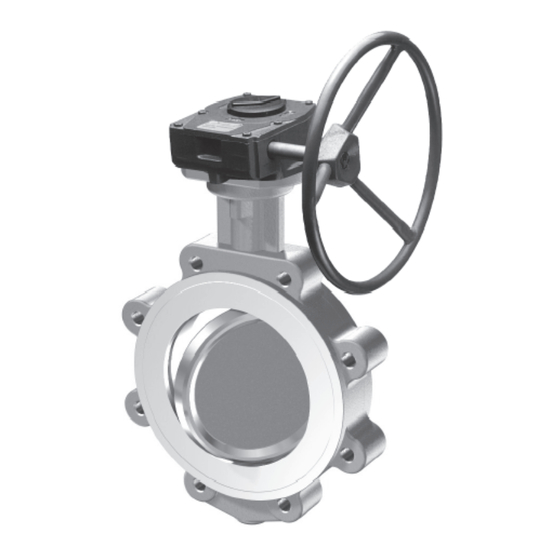
6 MG 71 en Fig. 3 Gearbox setscrew adjustment Fig. 4 Gearbox, series M 10. Put the plastic caps back on the setscrews. MAINTENANCE 11. Adjustment completed. Under normal conditions, the gearbox is maintenance free. The series M gearboxes can be used at ambient tempera- OPERATING INSTRUCTIONS tures from –20 to +120 °C. -
Page 6: Assembly Drawing And Parts List
6 MG 71 en ASSEMBLY DRAWING AND PARTS LIST Item Qty. Description Set-screw Worm Gasket Needle-Bearing Bushing Oil-seal Shaft Grease Position indicator Coverplate Quadrant Body Handwheel Spring type straight pin Hexagon head screw Head cap screw... - Page 7 6 MG 71 en DIMENSIONS ØZ N = number of holes Unit Bore size Valve mounting Dimensions, mm Hand Weight size flange no. of depth wheel Max. Ød, ISO 5211 holes kg / lbs with with stem ØZ/ height valve type input input...
-
Page 8: Type Code
**) Ensure the selection of the handwheel from technical bulletin 6MG21 (new) Metso Flow Control Inc. Europe, Vanha Porvoontie 229, P.O. Box 304, FI-01301 Vantaa, Finland. Tel. +358 20 483 150. Fax +358 20 483 151 North America, 44 Bowditch Drive, P.O. Box 8044, Shrewsbury, M A 01545, USA. Tel. +1 508 852 0200. Fax +1 508 852 8172 South America, Av.
Need help?
Do you have a question about the M Series and is the answer not in the manual?
Questions and answers