Table of Contents
Advertisement
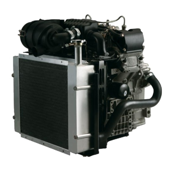
Thank you for purchasing Kipor KM2V80 series diesel engine. In order to ensure proper
operation, reliable running and good economic benefit of your machine, it is especially important
for you to operate correctly and maintain carefully. This manual will tell you how to operate and
maintain the machine correctly, it will also give you detail instruction about the main technical
specification, configuration and troubleshooting.
Content
Instruction of products.........................................................................................1
1. Brief instruction of products.........................................................................1
2. Composition of model and its meaning..........................................................1
3. External installation drawings and names of parts........................................... 2
4. Specification........................................................................................... 6
5. Main adjusting parameter........................................................................... 7
6. Tighten torque values of main bolts and nuts...................................................7
7. Fit clearance and interference table...............................................................8
Technical maintenance..........................................................................................9
2. Procedure of periodic maintenance.................................................................9
Disassembly and reassembly................................................................................ 13
1. Basic procedure of disassembly....................................................................13
2. Basic procedure of reassembly.....................................................................18
Check and maintenance.......................................................................................22
1. Cylinder cover......................................................................................... 22
2. Camshaft.......................................................................................................23
3. Piston and piston pin................................................................................. 24
4. Crankshaft............................................................................................. 25
5. Cylinder block and cylinder cover................................................................................
6. Lubrication system................................................................................... 27
7. Cooling system.......................................................................................
8. Fuel system..........................................................................................
The electrical system.......................................................................................
1. Starter motor.......................................................................................... 29
2. Heater plug.......................................................................................... .31
Troubleshooting and remedy of engine..................................................................35
Preliminary run.......................................................................................................................39
.............................................................9
27
28
29
Advertisement
Table of Contents

Subscribe to Our Youtube Channel
Related Manuals for Kipor KM2V80


Summary of Contents for Kipor KM2V80
- Page 1 Thank you for purchasing Kipor KM2V80 series diesel engine. In order to ensure proper operation, reliable running and good economic benefit of your machine, it is especially important for you to operate correctly and maintain carefully. This manual will tell you how to operate and maintain the machine correctly, it will also give you detail instruction about the main technical specification, configuration and troubleshooting.
-
Page 2: Instruction Of Products
Welcome you to purchase. 2. Composition of model and its meaning KM 2 V 80 Cylinder bore (mm) V-type Cylinder No. Kipor Introduction of products... -
Page 3: External Installation Drawings And Names Of Parts
3. External installation drawings and name of parts Please refer to picture 1, picture 2, picture 3 and picture 4 for details. Picture1 Vertical section view for KM2V80 diesel engine... - Page 4 Picture 2 Horizontal section view for KM2V80 diesel engine...
- Page 5 Picture 3 Vertical figuration view for KM2V80 diesel engine...
- Page 6 Picture 4 Horizontal figuration view for KM2V80 diesel engine...
-
Page 7: Specification
4. Specification Table 1 Main specification table of KM2V80 diesel engine Model KM2V80 Double cylinder, V-type, water-cooled, 4 stroke, Type swirl type Bore×Stroke mm 80×79 Displacement 0.794 Compression ratio Rated output/Rated speed 12.5/3000 14.5/3600 kW/r/min Max. torque N·m 49/1600~1800 Min. speed (zero load) r/min ≤900... - Page 8 5. Main adjusting specification Table 2 Main adjusting specification of KM2V80 diesel engine Item Standard value Cylinder compression clearance height 0.88~1.2 Advanced angle of fuel supply BTDC 18.5°±1° Fuel spraying pressure 13°±0.5° Valve timing Inlet valve Open at BTDC 22°...
-
Page 9: Fit Clearance And Interference Table
7. Fit clearance and interference table Table 4 Fit clearance and interference table Fitting clearance Name Standard dimension(mm) Remark (mm) +0.03 Cylinder inner diameter/ φ80H7 /d-0.515±0.01 0.565~0.635 Piston top outer diameter +0.03 Cylinder inner diameter/ φ80H7 /d-0.125±0.01 0.175~0.245 Piston skirt upper part +0.03 -0.06 Cylinder inner diameter/... - Page 10 +0.012 -0.035 Valve pipe/ Exhaust valve 0.035~0.062 φ6H7 /φ6 -0.050 +0.015 +0.055 Cylinder cover pipe hole/ φ10H7 /φ10 +0.045 -0.03~-0.055 Valve pipe +0.025 +0.12 Cylinder cover housing washer hole/ φ33.5H7 /φ33.5 +0.09 -0.065~-0.012 Inlet valve housing washer +0.021 +0.11 Cylinder cover housing washer hole/ φ28H7 /φ28 +0.09...
-
Page 11: Technical Maintenance
Technical maintenance 1. Daily check and periodic check Engine’ performance will be deteriorated if the operation condition becomes worse or time prolongs, such as: fuel and oil consumption increase, exhaust harmful substance increases, or vibratory and noise increase. Please strengthen the maintenance service of engine, insist on daily check and periodic maintenance, which will prove efficiency and prevent fault. - Page 12 ● pump and fuel injection pump ○:check :replace ●:Contact with Kipor agent 2. Procedure of periodic check 2.1 First 50h operation check At the beginning time of operation, the inner parts wear mutually and the lube oil is polluted soon, so please replace the lube oil and oil filter element.
- Page 13 Picture 6 Clean air filter places full of dust(such as quarrying plant, coal yard or road building plant), foreign matter inside the oil filter should be cleaned; Take out filter element parts from air filter shell, blow dust down with compression air. Please replace filter element parts if papery filter element is broken.
- Page 14 (3) Install the fuel inlet/exhaust pipe, turn on oil tank switch, and drain out air in fuel line, otherwise hard starting or stop running after starting will be resulted. 2.4.2 Replace cooling water: Drain out water after the cooling water is cooled down, in order to prevent be scalded by the splashing hot water.
- Page 15 a. Concrete steps (1) Refill the fuel injection pump with fuel, and revolve the flywheel in clockwise direction to the compression upper dead centre. Resolve the flywheel for several times until there is fuel flowing out. (2) Install the high pressure oil pipe tie which is used for measuring the oil supplying advance angle, then resolve the flywheel to drain out the air inside.
-
Page 16: Disassembly And Reassembly
Disassembly and reassembly of diesel engine 1. Basic procedure of disassembly (1) Prepare necessary room or container to store parts before disassembly, put each kind of bolt and screw as well as related parts together, in order to prevent possible mistaken. (2) Make sure what problem there is before disassembling;... -
Page 17: Cylinder Cover
picture 13 1.4 Disassemble fan gasket、fan impeller and fan seat (1) Loosen the four M6×25 bolts, which fix fan impeller and fan gasket and then remove the fan impeller and fan gasket. (2) Loosen the three M6×16 bolts which fix fan seat and then remove the fan seat. Refer to picture 14 picture 14 1.5 Disassembly the air conduct cover parts... - Page 18 inlet flange end. (2) Remove the inlet pressurizer tank parts. Refer to picture 16 picture 16 1.7 Disassemble the water pipe weldment (1) Loosen the M8X10 bolt which fixes the water pipe weldment on the crankcase cover (2) Loosen the hoop which connects the thermostat connection pipe and water outlet pipe. (3) Remove the water outlet pipe weldment.
- Page 19 1.9 Disassemble the rear support plate parts of starting motor and starting motor parts (1) Loosen the M10X20 bolt which fixes the rear support plate of starting motor on the engine side cover. (2) Loosen the two M10X30 bolts which fix the starting motor parts. (3) Remove the starting motor parts and rear support plate of starting motor.
- Page 20 picture 21 1.12 Disassemble the cylinder cover parts, valve push rod and cylinder cover gasket (1) Loosen the four cylinder cover bolts which fix the cylinder cover parts (2) Remove the cylinder cover parts, two valve push rods and cylinder cover gasket (3) Disassemble the cylinder cover parts in the same way.
- Page 21 1.14 Disassemble the flywheel parts and electromagnetic rotor parts (1) Loosen the four M10X32 flywheel bolts which fix the flywheel on the crankshaft. (2) Remove the flywheel parts and electromagnetic rotor parts. Refer to picture 24 picture 24 1.15 Disassemble the stator coil parts (1) Loosen the three M6X25 bolts and one bolt which fix the stator coil parts on the engine rear end.
-
Page 22: Camshaft
1.17 Disassemble the camshaft bearing cover and oil supplying camshaft. (1) Loosen the two M6X16 inner hexagonal bolts which fix the camshaft bearing cover (2) Remove the camshaft bearing cover and oil supplying camshaft. (3) Screw on the bearing cover. Refer to picture 27 picture 27 1.18 Disassemble the camshaft and valve tappet... - Page 23 (2) Take out the two piston connection rod assembly. (3) Reassemble the connection rod cover and connection rod bolt immediately after taking out the piston connection rod. (4) Mark the piston connection rod assembly of 1 cylinder and 2 cylinder. Refer to picture 30 picture 30 1.21 Disassemble the crankshaft parts...
- Page 24 2.2 Reassemble piston connecting rod assembly (1)Smear fresh oil on piston ring、piston pin、cylinder cover and connecting rod big-end hole. (2)The opening of piston ring should be staggered: the 1 ring and the 2 ring staggered 180°, the 2 ring and the 3 ring staggered 100°.
- Page 25 2.6 Reassemble the crankcase cover parts (1) Smear little seal gum on the crankcase cover. (2) Install the crankcase cover and fix it with seventeen M8X40 bolts. 2.7 Reassemble the stator coil parts (1) Install the stator coil parts on the flywheel end. (2) Fix it with three M6X25 bolts.
- Page 26 2.14 Reassemble the thermostat parts, water outlet pipe seat and water outlet connection pipe (1) Install the thermostat parts on the water outlet flange face of 1 cylinder cover and fix it with two M6X40 bolts. (2) Install the water outlet pipe seat on the water outlet flange face of 2 cylinder cover and fix it with two M6X20 bolts.
- Page 27 Check and maintain 1. Cylinder cover 1.1 Combustion chamber surface of cylinder cover Disassemble fuel injector、inlet valve and exhaust valve, clean the surface of combustion chamber and see whether there is any crack or other damage. Use smear infiltration to check minute crack.
- Page 28 Model KM2V80 Item Standard Valve sunken 0.5~0.7 mete Picture 33 Measure valve sunken mete (2) Check the seal conical surface of inlet/exhaust valve seat and observe the seal ring strip on the valve panel and valve seat ring. 1.3 Inlet/exhaust valve and valve pipe (1) Clean the gathered carton inside valve pipe;...
- Page 29 (2)Measure the valve spring verticality; revolve valve spring to see whether the whole side of valve spring is connected with the square ruler. Change valve spring if the measured verticality exceeds the limitation valve. Refer to picture 35 Table 8 Free length and verticality of valve spring KM2V80 Model Standard Item Valve spring free 39.5...
- Page 30 Picture 36 Measure lube oil clearance between rockshaft and valve rocker arm hole 1.6 Adjust valve clearance Adjust valve clearance when the generator is at cooling state. Refer to picture 37 Table 10 Clearance of inlet and exhaust valve Model KM2V80 Standard Item Inlet valve clearance 0.10~0.15 Exhaust valve clearance 0.10~0.15...
- Page 31 If the measured valve exceeds the limitation valve, please change camshaft. Refer to picture 39. Table 12 Fitting clearance between camshaft aperture and camshaft axial diameter Model KM2V80 Item Standard Service...
-
Page 32: Piston And Piston Pin
If the measured clearance exceeds the limitation valve, please change the camshaft. Refer to picture 41. Picture 41 Measure fitting clearance of camshaft aperture and axial diameter of oil supplying camshaft Model KM2V80 Item Standard Service limitation Camshaft aperture and 0.032~... - Page 33 If the clearance is too big, air leakage will be caused, and then result in leakage of lube oil. Refer to picture 43. Table 14 Clearance between piston ring and ring groove Model KM2V80 Standard Service Item...
- Page 34 Measure the outside diameter of piston pin, if the measured value exceeds the maintenance limitation, or has been grinded severely into echelon form, then you should replace the piston pin. Refer to picture 45. Table 16 Fitting clearance between piston pin hole diameter and piston pin diameter Model KM2V80 Item Standard Service limitation Piston pin hole diameter 0.025...
-
Page 35: Crankshaft
If the measured valuve exceeds the limitation value, please replace the piston pin and bushing. Table 18 Fitting clearance between connecting rod bushing hole diameter and piston pin diameter Model KM2V80 Item Standard Service limitation Connecting rod bushing 0.015~... - Page 36 If the measured value exceeds limitation value, please replace crankshaft or main bushing. Refer to picture 48. Table 20 Fitting clearance of main bearing hole and main axial diameter Model KM2V80 Standard Service Item...
- Page 37 If the measured value exceeds the limitation value, please change the oil pump parts. Refer to picture 50. Table 22 Clearance between outer rotor hole and outer rotor KM2V80 Model Standard Maintenance...
-
Page 38: Cooling System
Table 23 Clearance between rotor pump shaft hole and rotor pump shaft Model KM2V80 Item Standard Maintenance limitation Clearance 0.10 0.016~0.045 between rotor pump shaft hole and rotor pump shaft Picture 51 Measure the clearance between rotor pump shaft hole and rotor pump shaft 6.3 Axial clearance of oil pump... - Page 39 6mm, then read again the temperature. If the temperature is not in the leaving factory range, you should replace thermostat. Refer to picture Table 25 Temperature of thermostat Model KM2V80 Item Standard Opening 69.5 ~72.5...
-
Page 40: Fuel System
8 Fuel system 8.1 Check fuel injection pressure Install fuel injector on fuel injector tester, remove test handle of fuel injector slowly, and check the instant pressure when fuel is ejected out. If the measured valve is not within the limitation range, please replace fuel injection gasket. -
Page 41: Starter Motor
Starting System 1. Starter motor 1.1Check starter motor Refer to Fig 57 (1)Remove the motor excitation & armature winding outlet line from starter motor C wiring terminal (2)Connecting the motor case to battery anode with conducting wire. (3)When connecting the motor case to battery cathode with conducting wire, the motor should revolve, if not, please check the two windings of the motor. - Page 42 Fig 57 1.2 Check electromagnetic switch Refer to Fig 58 (1)Disassemble the starter motor from the base-frame of starter motor, and prepare a 6V battery. (2)Connect the electromagnetic switch case and C wiring terminal to battery cathode with two conducting wires. (3)Connect the battery anode and receptacle S with another conducting wire, now the gear shaft breaks cover suddenly.
- Page 43 1.4 Electromagnetic switch dismounting Refer to Fig 60 (1)Loose the three screws of end cover (2)Take off end cover 1 and magnet iron core. Fig 60 1.5 Decelerating clutch dismounting Refer to Fig 61 (1)Loose three bolts which tighten the driving shell ,(two are outside of motor, one is inside of motor), (2)Take off driving shell, clutch subassembly, steel ball, return spring and drive gear in turn.
- Page 44 Fig 62 Fig 63 (2)Measure diameter of commutator with outside micrometer, if the measured value is smaller than the limitation size, please change armature. (Refer Fig 63) ( 3 ) If there is much difference between excircle wire harness of commutator and axes parallelism, while the minimum size limitation of axial diameter is in the allowable range.
-
Page 45: Engine Electrical System
1.6.4 Check armature Refer to Fig 67 Check the electric conductivity with ohmmeter between the commutator copper sheet and the armature core or armature winding: (1) If the commutator copper sheet and armature core are current conducting, please replace armature. (2)If commutator copper sheet and armature winding are not current conducting, please replace armature. - Page 46 Fig.71 1.6.8 Check electromagnetic switch. Refer to Fig.72 Test electricity conductivity of contact disc in electromagnetic switch. Hold magnetic core with your thumb (Refer to Fig.68), test electricity conductivity between wire holder C and B. If no conductivity, please check contact and fastening between two wire holders and inner copper sheet.
- Page 47 Engine Troubleshooting (see Table26~Table33) Table 26 Fault of Alarm System Fault symptom Cause Remedy 1.Low oil level Add oil Oil Alarm 2.Oil filter is blocked Replace oil filter element 1 .Low cooling water level in Add cooling water radiator 2.Dirty radiator element Clean radiator element Temperature 3.Cooling water leak, cooling...
- Page 48 intake Dirty air filter element Clean filter element through pressure indicator compressive air or replace lamp Table 27 Fault Starting Fault sympt Cause Remedy 1.No fuel in fuel tank Add fuel 2 .Air existed in the fuel supply Eliminate air system 3...
- Page 49 Table 28 Abnormal smoke of exhaust air Fault symptom Cause Remedy 1.Overload for diesel engine Reduce the load 2.Blocked air filter Clean or replace air filter element 3.Unqualified fuel Use fuel with correct specification 4.Large air valve clearance Check and adjust air valve clearance 5.Blocked nozzle or leaked nozzle Check the injected fuel pressure and Black smoke...
- Page 50 is unsmooth. 4. There is leakage of fuel suction pipe Check the leakage and air exhaust connector, and air goes into the pipe. 5. The timing spring is softening, and Check and adjust the running speed of the running speed lower down. engine 6.
- Page 51 5. The injected frog of fuel injector is Check on the fuel pump test table in poor quality with fuel drop Table 31 Overheat of Engine Fault symptom Cause Remedy 1. Insufficient cooling water in water Add cooling water tank 2.
- Page 52 3. Blocked fuel filter element Replace fuel filter element 4 .No electricity of fuel pump electron Check circuit and electron magnetic stop magnetic stop valve, and cut the fuel valve supply Replace fuel pump 5. Fuel pump does not work properly Replace fuel injection pump 6.
- Page 53 Check the air valve clearance and valve 8. Large gear clearance, with knock noise timing and cylinder compress 9. Fuel injection is too early, and the noise Replace gear of hitting cylinder Check and adjust fuel supply timing 10.Blocked nozzle Clean or replace nozzle...
- Page 54 Preliminary operation Both new engine and repaired engine have to do preliminary operation. 1.1 Preparing work before starting Check all the bolts and nuts to make sure they are tightened. 1.2 Check and add fuel Check the left fuel level in the fuel tank, and add fuel if necessary. 1.3 Check and add oil Check the oil level in the oil base pan by oil dip stick, and add the same grade oil to the up limit if necessary.
Need help?
Do you have a question about the KM2V80 and is the answer not in the manual?
Questions and answers