
Related Manuals for WhisperKool QUANTUM Series


Summary of Contents for WhisperKool QUANTUM Series
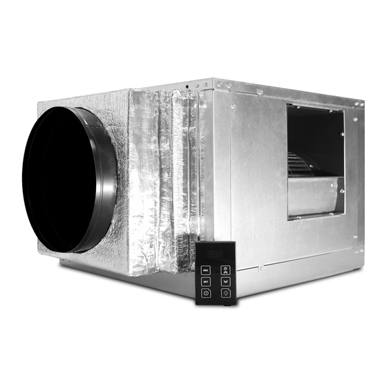
- Page 1 QUANTUM SERIES VERSION 4 TECHNICIAN’S MANUAL 24V Thermostat Conversion Kit Option Quantum SS9000 Quantum SS12000 The Coolest Thing In Wine Storage...
- Page 2 WhisperKOOL. Every effort has been made to ensure that the information in this manual is accurate. WhisperKOOL is not responsible for printing or clerical errors.
-
Page 3: Table Of Contents
System Operation......... . . 42 WhisperKOOL Troubleshooting Guide ..... . 45 Maintenance Schedule . - Page 4 WARNING Failure to follow the instructions provided in this manual may result in a poor vapor barrier, water damage, rust, and/or system corrosion and will void the warranty on your unit. The evaporator unit (fan coil unit) must be insulated using fiberglass insulation (R19 or higher).
-
Page 5: Introduction
INTRODUCTION Customer Service Thank you for purchasing a WhisperKOOL cooling system. We strive to provide the highest-quality products and the best possible customer service. If you have any questions about your system, please call us at 1-800-343-9463 or visit WhisperKOOL.com. -
Page 6: Quick Start Guide
WhisperKOOL units utilize a solenoid valve on the liquid line and a low-pressure switch on the suction line. When the thermostat calls for cooling, the solenoid valve opens, permitting the flow of refrigerant. The low-pressure switch then signals the compressor to cycle on. -
Page 7: Before You Start
10. WhisperKOOL requires that all split systems be installed by a certified HVAC-R technician only. NATE or equivalent is recommended. If you encounter a problem with your WhisperKOOL system, please refer to the Troubleshooting Guide. If you have any further questions or concerns, or need assistance, please contact WhisperKOOL’s Customer Service at 1-800-343-9463. Please be sure all testing has been completed prior to contacting Customer Service. -
Page 8: Receiving & Inspecting The System
RECEIVING & INSPECTING THE SYSTEM Upon receiving your WhisperKOOL unit: NOTE: WhisperKOOL units are manufactured in the USA and tested prior to shipment. • Use caution when lifting and check the package for damage. • Lift only at the designated hand-hold locations on the shipping container, or fully support the unit from underneath. A shipment may include one or more boxes containing accessories. -
Page 9: Quick Reference Guide
Quantum Series QUICK REFERENCE GUIDE Line set knockout options Power supply knockout Thermostat connection Return air Supply air Interchangeable panels Drain port Line set knockout Thermostat cable knockout options Power supply knockout www.whisperkool.com | Page 7... -
Page 10: Condensate Drain Pan
CONDENSATE DRAIN PAN Check local codes and regulations (regarding the disposal of condensates) for specific installation requirements. A separate drain line will need to be installed. Please see page 26 for more info. 020519 Page 8 | 1-800-343-9463... -
Page 11: Unit Specifications
100 line feet from evaporator unit. Thermostat Aftermarket (24V thermostat not included) Temp. Delta Can maintain a 55°F cellar temperature with up to 110°F condesner air intake temperature Warranty 2 years (parts and labor) www.whisperkool.com | Page 9... -
Page 12: Split System Checklist
SPLIT SYSTEM CHECKLIST In order to activate the warranty for this product, the information here must be complete and accurate. Any incorrect or omitted information will result in a return trip by the installing technician at their cost. DATA RECORDINGS Note: All readings need to be taken while the compressor is running. - Page 13 We recommend purchasing a unit with a larger capacity to compensate for these design limitations. Undersized cooling units can lead to premature failure and/or prevent the system from reaching the desired set temperature. As a result, they are not covered under warranty. www.whisperkool.com | Page 11...
-
Page 14: Blower Orientation Instructions
REAR BLOWER ORIENTATION INSTRUCTIONS 1. The Quantum unit is shipped with the blower and supply panel oriented to the right. If this is your desired orientation, proceed to the installation instructions on page 22. 2. To reorient the blower, first remove the access panels on the rear and top of the unit. 3. - Page 15 Quantum Series REAR BLOWER ORIENTATION INSTRUCTIONS, CONTINUED 4. Remove the six (6) screws securing the supply panel to the unit housing. 5. Remove the supply panel. 6. Rotate the blower to the rear configuration. www.whisperkool.com | Page 13...
- Page 16 REAR BLOWER ORIENTATION INSTRUCTIONS, CONTINUED 7. Attach supply panel to rear of unit using removed six (6) removed screws. 8. Secure blower to supply panel using the eight (8) screws removed earlier. 9. Reattach top panel with the six (6) screws removed earlier. Attach the panel which was formerly the rear panel on the right side of the unit where the supply panel was using the six (6) screws removed earlier.
- Page 17 (packaged with the unit) pictured below. The purpose of this piece of foam is to enable you to orient the blower so that the supply air duct faces upward. 1. To reorient the blower, first remove the access panels on the rear and top of the unit. www.whisperkool.com | Page 15...
- Page 18 TOP BLOWER ORIENTATION INSTRUCTIONS, CONTINUED 2. Next, remove the eight (8) screws securing the blower to the supply panel. 3. Remove the six (6) screws securing the supply panel to the unit housing. 4. Remove the panel. 020519 Page 16 | 1-800-343-9463...
- Page 19 TOP BLOWER ORIENTATION INSTRUCTIONS, CONTINUED 5. Pull blower out through the rear access panel. 6. Set the piece of foam shown on page 15 into the foam fan bracket on the bottom of the unit housing. www.whisperkool.com | Page 17...
- Page 20 TOP BLOWER ORIENTATION INSTRUCTIONS, CONTINUED 7. Slide the blower in from the rear and set upright on the piece of foam. BLOWER MOTOR NOTE: Make sure that the blower motor is closest to the side access panel as shown above. 020519 Page 18 | 1-800-343-9463...
- Page 21 8. Reattach the side panel using the eight (8) screws removed earlier. 9. Attach the supply panel to the top of the unit using the six (6) screws removed earlier. Then attach the blower to the panel using the eight (8) screws removed earlier. www.whisperkool.com | Page 19...
-
Page 22: Square-To-Round Plenum Installation Instructions
SQUARE-TO-ROUND PLENUM INSTALLATION* 1. Remove the backing from the double-sided tape on the flanges of the square-to-round plenum. 2. Stick the plenum onto the supply panel. NOTE: Make sure that the corners of the square-to-round plenum do not block the airflow from the blower. STICK HERE *Blower in rear orientation 020519... - Page 23 Quantum Series SQUARE-TO-ROUND PLENUM INSTALLATION, CONTINUED 3. Secure the square-to-round plenum to the housing with the provided #10-16 x 1/2” steel drilling screws 4. Seal all seams with foil tape. www.whisperkool.com | Page 21...
-
Page 24: Mounting The Evaporator Unit
MOUNTING THE EVAPORATOR UNIT T-square Minimum Tools Needed: Drill Level ¼” nut driver bit CPVC tube cutter INSTALLING THE EVAPORATOR 1. Locate the desired installation location. 2. If utilizing an external or secondary drip tray, ensure the drip tray is installed on a level surface. galvanized hanging straps. -
Page 25: System Wiring & Connections
Route the drain line from a proper discharge location to the evaporator installation location (see pages 26-28 for more drainage information). Route the thermostat wire into the evaporator unit (see page 24 for more thermostat wiring information). ITEMS TO ROUTE THERMOSTAT LINE SET DRAIN LINE POWER CABLE www.whisperkool.com | Page 23... -
Page 26: Thermostat Wiring Instructions
24V THERMOSTAT CONVERSION KIT WIRING INSTRUCTIONS The 24V thermostat conversion kit requires a standard 18-5 thermostat wire to be run from the evaporator unit to the thermostat. The white wire will not be used, as there is no heating function. (Some thermostats need a common wire and some do not;... -
Page 27: Installing The Evaporator Unit
Braze all connections on the evaporator unit. Install condensing unit (see pages 33-36 for instructions) before proceeding. Route the power wires into the unit. Connect the line voltage wire to the lever connector labeled “L. ” www.whisperkool.com | Page 25... -
Page 28: Drainage
DRAINAGE Condensation Drain Line The condensation drain line tube is used to remove excess condensation from the unit to a proper discharge location. It is important that the drain line tube be properly connected. The discharge location cannot be a secondary drain pan. Both condensate drain lines should discharge to different locations, and the secondary drain pan should discharge to an easily accessible and/or conspicuous location so the customer can monitor it. - Page 29 Plumbing Code relative to the material type. Condensate waste and drain line size shall be not less than 3/4 inch (19 mm) internal diameter and shall not decrease in size from the drain pan connection to the place of condensate disposal. www.whisperkool.com | Page 27...
-
Page 30: P-Trap Configuration
P-TRAP CONFIGURATION Below is a detailed diagram of how the P-trap should be constructed. ” CPVC cap with ” drilled hole (NOT SHOWN) ” CPVC cap ” CPVC tee UNIT 3” NOT TO SCALE ” THIS TEE MUST BE ROTATED SLIGHTLY TO ALLOW ACCESS TO CAP ”... -
Page 31: Quantum Evaporator Wiring Diagram
Blue Solenoid Relay Relay Blue Thermostat LEGEND Blue Field Installed Green Yellow Factory Installed Bare End BROWN BROWN LEGEND BLUE Field Installed Factory Installed DAYTON BLOWER 1XJY1 BLACK PURPLE BLACK CAPACITOR GREEN GREEN WHITE GREEN WHITE www.whisperkool.com | Page 29... -
Page 32: Preparing The Condensing Unit
Troubleshooting Guide on page 45. For the equipment warranty to be valid, WhisperKOOL requires that the installation is performed by a certified HVAC-R technician (a NATE-certified technician is recommended) per the specifications outlined in this technician’s manual. The technician shall be... -
Page 33: Quantum Ss9000 Condenser Wiring Diagram
Quantum Series QUANTUM SS9000 CONDENSER WIRING DIAGRAM www.whisperkool.com | Page 31... -
Page 34: Quantum Ss12000 Condenser Wiring Diagram
QUANTUM SS12000 CONDENSER WIRING DIAGRAM 020519 Page 32 | 1-800-343-9463... - Page 35 Quantum Series COPELAND COLD WEATHER START KIT WIRING DIAGRAM Black Black COPELAND 9,000 CWSK HEATER www.whisperkool.com | Page 33...
-
Page 36: Preparing The Condensing Unit (Continued)
PREPARING THE CONDENSING UNIT (CONTINUED) Installing the Condensing Unit The condensing unit can be installed inside a well-ventilated area of the home, but it is typically installed outside. Exterior applications will require the use of a protective housing, and the amount of sun exposure should be considered when selecting the placement of the condensing unit. -
Page 37: Installing The Condensing Unit
Option 2 should be used when the system is installed with the condensing unit at a higher elevation than the coil. LEGEND Liquid Line Solenoid Thermal Expansion Valve COMP Compressor Receiver EVAP. Evaporator O.D. Outer Diameter Option 2 www.whisperkool.com | Page 35... - Page 38 DO NOT BLOCK airflow through the INSTALLING THE CONDENSING UNIT exterior housing. This will restrict airflow and void the warranty. Refrigerant Piping Overview • Using the charts and illustrations found above, route the line set between the evaporator unit and condensing unit. Be sure to reference the chart for correct line set sizing.
- Page 39 • Confirm that the control is displaying the correct temperature and that no alarms are present. Charging Information A. Energize the solenoid valve on the evaporator unit by plugging the unit in and adjusting the thermostat to call for cooling. www.whisperkool.com | Page 37...
- Page 40 COPELAND WIRING PROCEDURE Copeland Wiring Procedure Step # Use a ¼” nut driver to remove the screws securing the cover to the compressor electrical compartment. Copeland Wiring Procedure Step # Remove the cover as shown. 020519 Page 38 | 1-800-343-9463...
- Page 41 Step # Pull the controller panel forward and rest it in the down position to expose the internal compartment. Copeland Wiring Procedure Step # Route the required 208/230V power wires into the open clamp on the enclosure. www.whisperkool.com | Page 39...
- Page 42 Copeland Wiring Procedure Step # Tighten the screws on the clamp to secure wire casing or conduit in place. Copeland Wiring Procedure Step # • Connect Line 1 wire to the L1 lever connector. • Connect Line 2 wire to the L2 lever connector. •...
- Page 43 Quantum Series Copeland Wiring Procedure Step # Push wires back into enclosure and place the controller panel back in place.. Copeland Wiring Procedure Step # Re-install cover. www.whisperkool.com | Page 41...
-
Page 44: System Operation
SYSTEM OPERATION The cooling system is equipped with the hardware needed to support a 24-volt air conditioning thermostat (not included). Initial Start-Up The condensing unit controller is preset at the factory. The Set the thermostat to COOL and fan switch to AUTO. Lower cut-in pressure is preset to 25psi and the cut-out pressure at the setpoint to the desired cellar temperature. - Page 45 High pressure trip lock-out alarm Module Failure Number of lock-outs For more information visit EmersonClimate.com/ElectronicUnitController Note: After 15 seconds of inactivity the controller will revert or call 1-888-367-9950 to the default display. www.whisperkool.com | Page 43...
- Page 46 Display Likely Causes Other Possible Causes Controller display remains • Unit power not properly applied - check for proper applied voltage • Power cable miswired – inspect cable, replace if blank after applying power • Power cable harness not plugged in properly or securely into the needed back of the controller –...
-
Page 47: Whisperkool Troubleshooting Guide
If so, contact the install- ing technician to assist with troubleshooting. System runs constantly Possible cause Solution Leaky door seal or poorly insulated cellar Fix leaky door seal and insulate cellar www.whisperkool.com | Page 45... - Page 48 Unit leaks water Possible cause Solution Evaporator unit is not level Evaporator unit should be level in ceiling to prevent leaking Drain line clogged or kinked Check drain line to make sure water can flow freely Drain is clogged, preventing water from escaping Remove 3/4”...
-
Page 49: Maintenance Schedule
2. Check wiring connections and integrity of cords 3. Pour a 50/50 bleach solution into the drain line every spring NOTE: For ducted systems, WhisperKOOL recommends filters with a mean efficiency reporting value (MERV) of 4 or better. Filters are not included with the unit. - Page 50 ADDING PAN TABS Pan tabs kill bacteria and related odors, remove sludge and scale, and help to prevent water damage caused by con- densate overflow. They are non-corrosive and easy to install. Simply remove any access panel to drop a pan tab into the drip tray every six weeks.
- Page 51 This can lead to a high concentration of the include proper clothing, gloves and eye protection. agent and possible corrosion of the tubing and/or base. www.whisperkool.com | Page 49...
-
Page 52: Technical Assistance
TECHNICAL ASSISTANCE WhisperKOOL Customer Service is available Monday through Friday from 6:00 a.m. to 4:00 p.m. Pacific Standard Time. The appointed customer service representative will be able to assist you with your questions and warranty information more effectively if you provide them with the following: •... -
Page 53: Installation Terms & Conditions
WhisperKOOL warrants against defects in material and workmanship as follows: 1. LABOR — For a period of two (2) years commencing on the date of purchase, WhisperKOOL will, at its option and discretion, reimburse up to $250 to the End User for cost incurred for servicing, repairing, removing or installing warranty parts. - Page 54 9. Removing the rivets from the Product’s unit housing without prior authorization from WhisperKOOL voids this limited warranty. 10. The End User must first contact WhisperKOOL Customer Service by telephone (at 1-800-343-9463) prior to attempting service on any Product still under the limited warranty; else the limited warranty is voided.
- Page 55 E. End User is responsible for all costs incurred for the installation and/or removal of the Product, or any part thereof, unless such cost has been agreed by WhisperKOOL to be a warranty repair prior to the work being performed.
- Page 56 Conditions of Sale shall be interpreted as through drafted jointly by WhisperKOOL and Purchaser. Any dispute will be resolved by the courts in and for the County of San Joaquin, State of California, and all parties, WhisperKOOL, Purchaser and End User, hereby irrevocably submit to the personal jurisdiction of such courts for that purpose. No waiver by WhisperKOOL of any breach or default of the contract of sale (including these Terms and Conditions of Sale) concerning a Product will be deemed to be a waiver of any preceding or subsequent breach or default.
- Page 57 E-mail: support@whisperkool.com Web: www.whisperkool.com B. Technical Assistance. WhisperKOOL Customer Service is available Monday through Friday from 6:00 a.m. to 4:00 p.m. PST. The Customer Service representative will be able to assist you with your questions and warranty information more effectively if you provide them with the following: 1.
- Page 58 WhisperKOOL 1738 E. Alpine Ave Stockton, CA 95205 1-800-343-9463 www.whisperkool.com...
Need help?
Do you have a question about the QUANTUM Series and is the answer not in the manual?
Questions and answers