Table of Contents
Advertisement
Available languages
Available languages
Quick Links
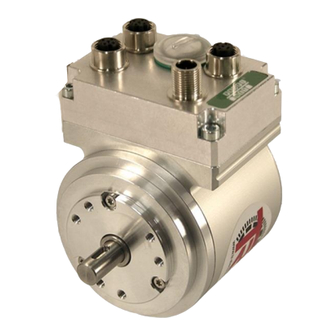
Absolute Encoder CD_-75
PROFINET IO/PROFIsafe
Parametrierung mit SIEMENS SIMATIC S7-1500
und -300/400 Steuerungssystemen /
Parameterization with SIEMENS SIMATIC S7-1500
and -300/400 control systems
CDH 75 M
_Sicherheitsprogramm erstellen
- Konfigurationsbeispiel
_Zugriff auf den sicherheitsgerichteten Datenkanal
_Festlegen der Parameter / CRC-Berechnung
_Safety Program Creation
- Configuration Example
_Access to the safety-oriented data channel
_Parameter Definition / CRC Calculation
D
Seite 2 - 80
GB
Page 81 - 159
CDV 75 M
Technical
Information
Advertisement
Chapters
Table of Contents

Related Manuals for TR-Electronic CD-75 Series


Summary of Contents for TR-Electronic CD-75 Series
- Page 1 Seite 2 - 80 Page 81 - 159 Absolute Encoder CD_-75 PROFINET IO/PROFIsafe Parametrierung mit SIEMENS SIMATIC S7-1500 und -300/400 Steuerungssystemen / Parameterization with SIEMENS SIMATIC S7-1500 and -300/400 control systems CDH 75 M CDV 75 M _Sicherheitsprogramm erstellen - Konfigurationsbeispiel _Zugriff auf den sicherheitsgerichteten Datenkanal _Festlegen der Parameter / CRC-Berechnung _Safety Program Creation...
- Page 2 PROFIBUS™, PROFINET™ und PROFIsafe™, sowie die zugehörigen Logos, sind eingetragene Warenzeichen der PROFIBUS Nutzerorganisation e.V. (PNO). SIMATIC und TIA Portal sind eingetragene Warenzeichen der SIEMENS AG TR-Electronic GmbH 2016, All Rights Reserved Printed in the Federal Republic of Germany Page 2 of 159...
-
Page 3: Table Of Contents
4.5 Übersetzen der Hardware- und Software-Projektdaten ............43 4.6 Sicherheitsprogramm laden ....................45 4.7 Sicherheitsprogramm testen ....................48 TR-Electronic GmbH 2016, All Rights Reserved Printed in the Federal Republic of Germany 09/20/2016 TR - ECE - TI - DGB - 0292 - 01... - Page 4 6.4.1 Nach Anlauf des F-Systems ................... 78 6.4.2 Nach Kommunikationsfehlern ................. 78 7 Software-, Beispiel- und Bibliotheken-Download ..........79 TR-Electronic GmbH 2016, All Rights Reserved Printed in the Federal Republic of Germany Page 4 of 159 TR - ECE - TI - DGB - 0292 - 01...
- Page 5 Änderungs-Index Änderung Datum Index Erstausgabe 20.04.16 20.09.16 Englische Übersetzung hinzugefügt TR-Electronic GmbH 2016, All Rights Reserved Printed in the Federal Republic of Germany 09/20/2016 TR - ECE - TI - DGB - 0292 - 01 Page 5 of 159...
-
Page 6: Allgemeines
TR-ECE-BA-D-0107 ● schnittstellenspezifische Benutzerhandbuch TR-ECE-BA-D-0095 ● und diese optionale „Technische Information“ TR-Electronic GmbH 2016, All Rights Reserved Printed in the Federal Republic of Germany Page 6 of 159 TR - ECE - TI - DGB - 0292 - 01... -
Page 7: Sicherheitshinweise
2.3 Personalqualifikation Die Konfiguration des Mess-Systems darf nur von qualifiziertem Fachpersonal durchgeführt werden, siehe SIEMENS Handbuch. TR-Electronic GmbH 2016, All Rights Reserved Printed in the Federal Republic of Germany 09/20/2016 TR - ECE - TI - DGB - 0292 - 01... -
Page 8: Nutzungsbedingungen Der Softwarebeispiele
Die zum Download angebotenen Softwarebeispiele dienen ausschließlich zu Demonstrationszwecken, der Einsatz durch den Anwender erfolgt auf eigene Gefahr. TR-Electronic GmbH 2016, All Rights Reserved Printed in the Federal Republic of Germany Page 8 of 159 TR - ECE - TI - DGB - 0292 - 01... -
Page 9: Festlegen Der Parameter / Crc-Berechnung
Gerätesicht Inspektorfenster unter Eigenschaften -> Allgemein -> PROFIsafe zu finden, siehe auch Kapitel „Einstellen der iParameter“ auf Seite 29. TR-Electronic GmbH 2016, All Rights Reserved Printed in the Federal Republic of Germany 09/20/2016 TR - ECE - TI - DGB - 0292 - 01... -
Page 10: Crc-Berechnung Über Die Iparameter
Open template... die zum Mess-System mitgelieferte Vorlagendatei (hier als Beispiel: CDx75M_EPN_002.xml) öffnen. TR-Electronic GmbH 2016, All Rights Reserved Printed in the Federal Republic of Germany Page 10 of 159 TR - ECE - TI - DGB - 0292 - 01... - Page 11 F_iPar_CRC-Wert und die geänderten Parameter sind bei der Projektierung im TIA Portal V13 einzutragen. Siehe Kap.: 4.3.1 „Einstellen der iParameter“ auf Seite 29 und Kap.: 4.3.2 „Einstellen der F-Parameter“ auf Seite 30. TR-Electronic GmbH 2016, All Rights Reserved Printed in the Federal Republic of Germany 09/20/2016...
-
Page 12: F-Parameter
F-Parameter F_Par_CRC, welcher bei der Projektierung des Mess-Systems in der Gerätesicht im Inspektorfenster unter Eigenschaften -> Allgemein -> PROFIsafe angezeigt wird. Siehe auch Kapitel „Einstellen der F-Parameter“ auf Seite TR-Electronic GmbH 2016, All Rights Reserved Printed in the Federal Republic of Germany Page 12 of 159... -
Page 13: Nicht Einstellbare F-Parameter
Jede Parameteränderung ergibt ein neuer F_Par_CRC-Wert, welcher wie oben dargestellt, angezeigt wird. Ist bereits ein Sicherheitsprogramm vorhanden, muss dieses neu generiert werden. TR-Electronic GmbH 2016, All Rights Reserved Printed in the Federal Republic of Germany 09/20/2016 TR - ECE - TI - DGB - 0292 - 01... -
Page 14: Sicherheitsprogramm Erstellen - Konfigurationsbeispiel
● Das Offline-Passwort ist Teil des Sicherheitsprogramms im Offline-Projekt auf dem Programmiergerät. ● Das Online-Passwort ist Teil des Sicherheitsprogramms in der F-CPU. TR-Electronic GmbH 2016, All Rights Reserved Printed in the Federal Republic of Germany Page 14 of 159... -
Page 15: Voraussetzungen
● Profilschiene (6ES7 590-1AB60-0AA0) ● Spannungsversorgung „PM 1507“ (6EP1332-4BA00) ● F-CPU-Einheit „CPU1511F-1 PN“ (6ES7511-1FK01-0AB0) TR-Electronic GmbH 2016, All Rights Reserved Printed in the Federal Republic of Germany 09/20/2016 TR - ECE - TI - DGB - 0292 - 01... -
Page 16: Hardware-Konfiguration
Das TIA Portal V13 starten und ein neues Projekt anlegen. Das Geräte & Netze Portal öffnen und Neues Gerät hinzufügen anwählen. TR-Electronic GmbH 2016, All Rights Reserved Printed in the Federal Republic of Germany Page 16 of 159... - Page 17 Im Arbeitsbereich ist die Gerätesicht mit der Profilschiene und der CPU 1511F-1 PN angewählt. Auf der rechten Seite ist der Hardwarekatalog geöffnet. TR-Electronic GmbH 2016, All Rights Reserved Printed in the Federal Republic of Germany 09/20/2016 TR - ECE - TI - DGB - 0292 - 01...
- Page 18 Installationsverzeichnis des TIA Portal V13 kopieren. Es ist zu beachten, dass die Verzeichnisstruktur variieren kann. TR-Electronic GmbH 2016, All Rights Reserved Printed in the Federal Republic of Germany Page 18 of 159 TR - ECE - TI - DGB - 0292 - 01...
- Page 19 GSDML-Datei wird Projektansicht TIA Portal V13 ohne eine Auswahl im Arbeitsbereich geöffnet. TR-Electronic GmbH 2016, All Rights Reserved Printed in the Federal Republic of Germany 09/20/2016 TR - ECE - TI - DGB - 0292 - 01 Page 19 of 159...
- Page 20 Doppelklick, mit der linken Maustaste auf das Symbol CD_75_-EPN MRP V2.3, auswählen. Das Mess-System wird jetzt im Arbeitsbereich in der Netzsicht angezeigt. TR-Electronic GmbH 2016, All Rights Reserved Printed in the Federal Republic of Germany Page 20 of 159...
- Page 21 Im Auswahlmenü das sich öffnet, die Profinet Schnittstelle der Steuerung, im PLC_1.PROFINET-Schnittstelle_1, Beispielprojekt Schnittstelle anwählen. TR-Electronic GmbH 2016, All Rights Reserved Printed in the Federal Republic of Germany 09/20/2016 TR - ECE - TI - DGB - 0292 - 01 Page 21 of 159...
-
Page 22: Eigenschaften Der Hardware-Konfiguration Festlegen
Für die Einstellung der Steuerungseigenschaften muss in der Netzansicht die Steuerung angewählt werden. Die Auswahl ist durch einen Rand gekennzeichnet. TR-Electronic GmbH 2016, All Rights Reserved Printed in the Federal Republic of Germany Page 22 of 159 TR - ECE - TI - DGB - 0292 - 01... - Page 23 Unterhalb der Netzsicht werden im Inspektorfenster, nach Auswahl des Registers Eigenschaften -> Allgemein, die Steuerungseigenschaften angezeigt. TR-Electronic GmbH 2016, All Rights Reserved Printed in the Federal Republic of Germany 09/20/2016 TR - ECE - TI - DGB - 0292 - 01...
- Page 24 Einstellung Vollzugriff inkl. Fail-safe (kein Schutz)ist ein Passwort zu vergeben. Im Beispielprojekt wird das Passwort „pw_fcpu“ verwendet. TR-Electronic GmbH 2016, All Rights Reserved Printed in the Federal Republic of Germany Page 24 of 159 TR - ECE - TI - DGB - 0292 - 01...
- Page 25 -> Schnittstellen-Optionen ausgewählt. In der Maske muss der Haken bei Gerätetausch ohne Wechselmedium ermöglichen entfernt werden. TR-Electronic GmbH 2016, All Rights Reserved Printed in the Federal Republic of Germany 09/20/2016 TR - ECE - TI - DGB - 0292 - 01...
- Page 26 IP-Adresse und die Subnetzmaske eingestellt werden. Die IP-Adresse wird mit dem Download des Projekts durch den PG/PC eingestellt. In der Maske kann unter PROFINET der Gerätename festgelegt werden. TR-Electronic GmbH 2016, All Rights Reserved Printed in the Federal Republic of Germany Page 26 of 159...
- Page 27 Verbindung zum Ethernet-Netzwerk einzustellen. Danach muss die Schaltfläche Liste aktualisieren angewählt werden. TR-Electronic GmbH 2016, All Rights Reserved Printed in the Federal Republic of Germany 09/20/2016 TR - ECE - TI - DGB - 0292 - 01...
- Page 28 Schaltfläche Schließen beendet werden. Im Auslieferungszustand, sowie nach einer Rücksetzung, hat das Mess-System keinen Gerätenamen gespeichert. TR-Electronic GmbH 2016, All Rights Reserved Printed in the Federal Republic of Germany Page 28 of 159 TR - ECE - TI - DGB - 0292 - 01...
-
Page 29: Parametrierung
Arbeitsbereichs zunächst in dem auf der rechten Seite angezeigten Register Geräteübersicht der Eintrag CD_75_-EPN E/A_1 mit der linken Maustaste angewählt werden. TR-Electronic GmbH 2016, All Rights Reserved Printed in the Federal Republic of Germany 09/20/2016 TR - ECE - TI - DGB - 0292 - 01... -
Page 30: Einstellen Der F-Parameter
Arbeitsbereichs zunächst in dem auf der rechten Seite angezeigten Register Geräteübersicht der Eintrag CD_75_-EPN E/A safety_1 mit der linken Maustaste angewählt werden. TR-Electronic GmbH 2016, All Rights Reserved Printed in the Federal Republic of Germany Page 30 of 159... - Page 31 Voraussetzung ist lediglich, dass die F-CPU die Fehlersicherheit aktiviert hat. (Siehe Kap.: 4.2.1 „Eigenschaften der Hardware-Konfiguration festlegen“ auf Seite 22). TR-Electronic GmbH 2016, All Rights Reserved Printed in the Federal Republic of Germany 09/20/2016 TR - ECE - TI - DGB - 0292 - 01...
-
Page 32: Erstellen Der Fehlenden (F-)Bausteine
Abständen aufgerufen und durchlaufen. Nach Abarbeitung Sicherheitsprogramms wird Standard- Anwenderprogramm weiterbearbeitet. TR-Electronic GmbH 2016, All Rights Reserved Printed in the Federal Republic of Germany Page 32 of 159 TR - ECE - TI - DGB - 0292 - 01 09/20/2016... -
Page 33: F-Ablaufgruppe
Maustaste angewählt werden. Hier können die Einstellungen für die Ablaufgruppe angepasst werden. Im Beispielprojekt werden die Default Einstellungen verwendet. TR-Electronic GmbH 2016, All Rights Reserved Printed in the Federal Republic of Germany 09/20/2016 TR - ECE - TI - DGB - 0292 - 01... - Page 34 Schaltfläche Einrichten mit der linken Maustaste angewählt werden. Dadurch öffnet sich das Fenster Passwort einrichten, in dem das Passwort festgelegt wird. Im Beispielprojekt wird das Passwort „pw_fprog“ verwendet. TR-Electronic GmbH 2016, All Rights Reserved Printed in the Federal Republic of Germany Page 34 of 159...
- Page 35 Doppelklick mit der linken Maustaste angewählt werden. Dadurch wird ein Fenster geöffnet in dem der Bausteine hinzugefügt werden kann. TR-Electronic GmbH 2016, All Rights Reserved Printed in the Federal Republic of Germany 09/20/2016 TR - ECE - TI - DGB - 0292 - 01...
-
Page 36: Generieren Der Organisationsbausteine (Obs)
Neuen Baustein hinzufügen durch einen Doppelklick der linken Maustaste ausgewählt werden. TR-Electronic GmbH 2016, All Rights Reserved Printed in the Federal Republic of Germany Page 36 of 159 TR - ECE - TI - DGB - 0292 - 01... -
Page 37: Programmieren Der F-Bausteine (Anwenderquittierung)
Projektnavigation im Verzeichnisbaum unter dem Verzeichnis CD_75_- EPN_PROFIsafe -> PLC_1 [CPU 1511F-1 PN] -> Programmbausteine -> Systembausteine -> STEP7 Safety -> F-Peripherie-DBs zu finden. TR-Electronic GmbH 2016, All Rights Reserved Printed in the Federal Republic of Germany 09/20/2016 TR - ECE - TI - DGB - 0292 - 01... - Page 38 Doppelklick der linken Maustaste angewählt, so öffnet sich im Arbeitsbereich der Baustein im Programmeditor. Auf der rechten Seite werden für die Programmierung verwendbare Anweisungen aufgelistet. TR-Electronic GmbH 2016, All Rights Reserved Printed in the Federal Republic of Germany Page 38 of 159...
- Page 39 An den Ausgang der Und-Box wird eine Zuweisung-Box angeschlossen. Dieser wird das Signal ACK_REI des Mess-System F-Peripherie-DBs mit der Bezeichnung ˮF00000_CD_75_-EPNE/Asafety_1ˮ.ACK_REI zugewiesen. TR-Electronic GmbH 2016, All Rights Reserved Printed in the Federal Republic of Germany 09/20/2016 TR - ECE - TI - DGB - 0292 - 01...
-
Page 40: Programmieren Der F-Bausteine (Eingangsdaten Speichern)
Adresse: %IW8 Geschwindigkeit: Name: IN_Speed_Safety Datentyp: Int Adresse: %IW4 TR-Electronic GmbH 2016, All Rights Reserved Printed in the Federal Republic of Germany Page 40 of 159 TR - ECE - TI - DGB - 0292 - 01 09/20/2016... - Page 41 Startwert: 0 Geschwindigkeit: Name: Safety_Speed Datentyp: Int Startwert: 0 TR-Electronic GmbH 2016, All Rights Reserved Printed in the Federal Republic of Germany 09/20/2016 TR - ECE - TI - DGB - 0292 - 01 Page 41 of 159...
- Page 42 Datenbaustein angeschlossen. Für die „Position-Singleturn“ und für die „Geschwindigkeit“ wird dieser Vorgang mit den entsprechenden Eingangs- und Ausgangsvariablen wiederholt. TR-Electronic GmbH 2016, All Rights Reserved Printed in the Federal Republic of Germany Page 42 of 159 TR - ECE - TI - DGB - 0292 - 01...
-
Page 43: Übersetzen Der Hardware- Und Software-Projektdaten
Verzeichnisbaum Eintrag EPN_PROFIsafe -> PLC_1 [CPU 1511F-1 PN] mit der linken Maustaste angewählt werden. TR-Electronic GmbH 2016, All Rights Reserved Printed in the Federal Republic of Germany 09/20/2016 TR - ECE - TI - DGB - 0292 - 01... - Page 44 Danach kann in der Menüleiste unter Bearbeiten der Befehl Übersetzen angewählt werden oder das entsprechenden Symbol aus der Funktionsleiste. TR-Electronic GmbH 2016, All Rights Reserved Printed in the Federal Republic of Germany Page 44 of 159 TR - ECE - TI - DGB - 0292 - 01...
-
Page 45: Sicherheitsprogramm Laden
Danach kann in der Menüleiste unter Online der Befehl Laden in Gerät oder das entsprechenden Symbol aus der Funktionsleiste angewählt werden. TR-Electronic GmbH 2016, All Rights Reserved Printed in the Federal Republic of Germany 09/20/2016 TR - ECE - TI - DGB - 0292 - 01... - Page 46 Nach Anwahl des Befehls wird das Fenster Vorschau Laden geöffnet. Ein Laden des Projekts ist aber noch nicht möglich, da einige Voraussetzungen noch nicht erfüllt sind. TR-Electronic GmbH 2016, All Rights Reserved Printed in the Federal Republic of Germany Page 46 of 159...
- Page 47 Nachdem das Projekt in die F-CPU geladen wurde muss im Fenster Vorschau Laden die Schaltfläche Fertig stellen angewählt werden. TR-Electronic GmbH 2016, All Rights Reserved Printed in the Federal Republic of Germany 09/20/2016 TR - ECE - TI - DGB - 0292 - 01...
-
Page 48: Sicherheitsprogramm Testen
Beobachtung Eingangsdaten werden unter Name die Variablen „IN_Multi_Safety“, „IN_Single_Safety“ und „IN_Speed_Safety“ eingetragen. TR-Electronic GmbH 2016, All Rights Reserved Printed in the Federal Republic of Germany Page 48 of 159 TR - ECE - TI - DGB - 0292 - 01... - Page 49 Steuerwert das entsprechende Feld mit der rechten Maustaste angewählt wird. Dadurch öffnet sich ein Kontextmenü. Im Menü ist der Eintrag Steuern -> Steuern auf 1 mit der linken Maustaste anzuwählen. TR-Electronic GmbH 2016, All Rights Reserved Printed in the Federal Republic of Germany 09/20/2016...
- Page 50 Nach ausführen der Anwenderquittierung haben die Safe Eingangsdaten gültige Werte. Jetzt kann über das Kontextmenü die Variable ˮTag_1ˮ wieder auf FALSE (Steuern auf 0) gesteuert werden. TR-Electronic GmbH 2016, All Rights Reserved Printed in the Federal Republic of Germany Page 50 of 159...
-
Page 51: Sicherheitsprogramm Erweitern - Anwendungsbeispiele
Seite 78. Der Preset-Baustein führt keine Überprüfung der neuen Position durch. Dies muss durch den Anwender umgesetzt werden! TR-Electronic GmbH 2016, All Rights Reserved Printed in the Federal Republic of Germany 09/20/2016 TR - ECE - TI - DGB - 0292 - 01... -
Page 52: Parameter Beschreibung
In den Ausgangsdaten des Mess-Systems an Register TR-Control1 am Pin 2 ausgeben. TR-Electronic GmbH 2016, All Rights Reserved Printed in the Federal Republic of Germany Page 52 of 159 TR - ECE - TI - DGB - 0292 - 01... -
Page 53: Funktionsbeschreibung
Mit dem Rücksetzen des Eingangs TR_IPAR_OK wird der Ausgang BUSY wieder auf 0 zurückgesetzt. Die Ausführung des Preset-Bausteins ist damit beendet. TR-Electronic GmbH 2016, All Rights Reserved Printed in the Federal Republic of Germany 09/20/2016 TR - ECE - TI - DGB - 0292 - 01... - Page 54 Bereich: Eingangssignale Preset-Baustein oranger Bereich: Ausgangssignale Preset-Baustein grüner Bereich: „TR-Geber“ Mess-System-Funktion bzw. Mess-System-Werte TR-Electronic GmbH 2016, All Rights Reserved Printed in the Federal Republic of Germany Page 54 of 159 TR - ECE - TI - DGB - 0292 - 01...
- Page 55 Timing-Diagramm der Preset-Justage-Funktion wenn TR_QBAD den Wert 1 hat. blauer Bereich: Eingangssignale Preset-Baustein oranger Bereich: Ausgangssignale Preset-Baustein TR-Electronic GmbH 2016, All Rights Reserved Printed in the Federal Republic of Germany 09/20/2016 TR - ECE - TI - DGB - 0292 - 01...
-
Page 56: Baustein Erstellung
öffnen der Haken gesetzt werden. Durch betätigen der OK- Schaltfläche wird der Funktionsbaustein angelegt und im Programmeditor geöffnet. TR-Electronic GmbH 2016, All Rights Reserved Printed in the Federal Republic of Germany Page 56 of 159 TR - ECE - TI - DGB - 0292 - 01... - Page 57 Um die Funktionalität der Preset-Justage-Funktion zu realisieren müssen die folgenden Netzwerke im Preset-Baustein erstellt werden. TR-Electronic GmbH 2016, All Rights Reserved Printed in the Federal Republic of Germany 09/20/2016 TR - ECE - TI - DGB - 0292 - 01...
- Page 58 Sicherheitsprogramm erweitern – Anwendungsbeispiele TR-Electronic GmbH 2016, All Rights Reserved Printed in the Federal Republic of Germany Page 58 of 159 TR - ECE - TI - DGB - 0292 - 01 09/20/2016...
- Page 59 Es ist besonders darauf zu achten, dass der Eingang TR_Pres_Error und der Ausgang TR_Pres_Request an das richtige Bit des Mess-Systems angeschlossen wird! TR-Electronic GmbH 2016, All Rights Reserved Printed in the Federal Republic of Germany 09/20/2016 TR - ECE - TI - DGB - 0292 - 01...
- Page 60 Sicherheitsprogramm erweitern – Anwendungsbeispiele TR-Electronic GmbH 2016, All Rights Reserved Printed in the Federal Republic of Germany Page 60 of 159 TR - ECE - TI - DGB - 0292 - 01 09/20/2016...
-
Page 61: Herstellerspezifische Fehlerauswertung
5.2 Herstellerspezifische Fehlerauswertung Das Mess-System liefert im Fehlerfall einen herstellerspezifische Diagnosenachricht. Da dieser mehrere hundert Fehlercodes generieren kann, muss der Fehlercode zur Auswertung an die Firma TR-Electronic übermittelt werden. herstellerspezifische Diagnosenachricht konnte SIEMENS SIMATIC Manager Projektierungssoftware über Hardwarekonfiguration ausgelesen werden. In der SIEMENS Projektierungssoftware TIA Portal ist dies leider nicht mehr möglich. -
Page 62: Parameter Beschreibung
0x0005 = Fehler: Diagnose ID ist falsch 4 Byte Wert mit dem herstellerspezifischen TR_Manuf_Error DWORD Fehler TR-Electronic GmbH 2016, All Rights Reserved Printed in the Federal Republic of Germany Page 62 of 159 TR - ECE - TI - DGB - 0292 - 01 09/20/2016... -
Page 63: Funktionsbeschreibung
Wenn der Lesezugriff nicht erfolgreich war, kann über den Ausgang STATUS der Fehler ermittelt werden. Beim Lesefehler durch den Baustein RDREC wird zusätzlich noch der Fehlerwert des Bausteins am Ausgang ERRVAL angezeigt. TR-Electronic GmbH 2016, All Rights Reserved Printed in the Federal Republic of Germany 09/20/2016... - Page 64 Bereich: Eingangssignale Manufacturer-Error-Baustein oranger Bereich: Ausgangssignale Manufacturer-Error-Baustein grüner Bereich: „TR-Geber“ Mess-System-Funktion TR-Electronic GmbH 2016, All Rights Reserved Printed in the Federal Republic of Germany Page 64 of 159 TR - ECE - TI - DGB - 0292 - 01...
- Page 65 Lesebuffers erkannt wird. blauer Bereich: Eingangssignale Manufacturer-Error-Baustein oranger Bereich: Ausgangssignale Manufacturer-Error-Baustein grüner Bereich: „TR-Geber“ Mess-System-Funktion TR-Electronic GmbH 2016, All Rights Reserved Printed in the Federal Republic of Germany 09/20/2016 TR - ECE - TI - DGB - 0292 - 01...
-
Page 66: Baustein Erstellung
Informationen bei Neu hinzufügen und öffnen der Haken gesetzt werden. Durch betätigen der OK-Schaltfläche wird der Funktionsbaustein angelegt und im Programmeditor geöffnet. TR-Electronic GmbH 2016, All Rights Reserved Printed in the Federal Republic of Germany Page 66 of 159... - Page 67 Um den herstellerspezifischen Fehler auszulesen müssen die folgenden Netzwerke im Manufacturer-Error-Baustein erstellt werden. TR-Electronic GmbH 2016, All Rights Reserved Printed in the Federal Republic of Germany 09/20/2016 TR - ECE - TI - DGB - 0292 - 01...
- Page 68 Feld Nummer: Manuell 170 einzutragen. Durch betätigen der OK-Schaltfläche wird der Datenbaustein angelegt. TR-Electronic GmbH 2016, All Rights Reserved Printed in the Federal Republic of Germany Page 68 of 159 TR - ECE - TI - DGB - 0292 - 01...
- Page 69 TR-Electronic GmbH 2016, All Rights Reserved Printed in the Federal Republic of Germany 09/20/2016 TR - ECE - TI - DGB - 0292 - 01 Page 69 of 159...
- Page 70 Sicherheitsprogramm erweitern – Anwendungsbeispiele TR-Electronic GmbH 2016, All Rights Reserved Printed in the Federal Republic of Germany Page 70 of 159 TR - ECE - TI - DGB - 0292 - 01 09/20/2016...
- Page 71 TR-Electronic GmbH 2016, All Rights Reserved Printed in the Federal Republic of Germany 09/20/2016 TR - ECE - TI - DGB - 0292 - 01 Page 71 of 159...
- Page 72 Name: TR_Manufacturer_Error_DB einzutragen. Durch betätigen des OK-Schaltfläche wird der Datenbaustein angelegt. TR-Electronic GmbH 2016, All Rights Reserved Printed in the Federal Republic of Germany Page 72 of 159 TR - ECE - TI - DGB - 0292 - 01...
- Page 73 Dazu wurden Beispielprojekt entsprechenden Variablen angelegt und der Baustein damit verbunden. TR-Electronic GmbH 2016, All Rights Reserved Printed in the Federal Republic of Germany 09/20/2016 TR - ECE - TI - DGB - 0292 - 01 Page 73 of 159...
-
Page 74: Zugriff Auf Den Sicherheitsgerichteten Datenkanal
Daten des CD_75_-EPN E/A safety_1-Moduls abhängig von bestimmten Zuständen des Sicherheitsprogramms passiviert werden sollen, z.B. Gruppenpassivierung TR-Electronic GmbH 2016, All Rights Reserved Printed in the Federal Republic of Germany Page 74 of 159 TR - ECE - TI - DGB - 0292 - 01... -
Page 75: Mess-System F-Peripherie-Db „Db30002" - Variablenübersicht
Sicherheitsgründen müssen diese Fehler erst beseitigt werden und anschließend die Versorgungsspannung AUS/EIN geschaltet werden. TR-Electronic GmbH 2016, All Rights Reserved Printed in the Federal Republic of Germany 09/20/2016 TR - ECE - TI - DGB - 0292 - 01... -
Page 76: Ack_Rei
QBAD = 1 gesetzt. PASS_OUT ändert seinen Wert bei einer Passivierung über PASS_ON = 1 nicht. PASS_OUT kann deshalb zur Gruppenpassivierung weiterer F-Peripherien verwendet werden. TR-Electronic GmbH 2016, All Rights Reserved Printed in the Federal Republic of Germany Page 76 of 159... -
Page 77: Ack_Req
Auf die Variablen des F-Peripherie-DBs kann durch Angabe des Namens des F-Peripherie-DBs und durch Angabe des Namens der Variablen zugegriffen werden: „vollqualifizierter DB-Zugriff“. TR-Electronic GmbH 2016, All Rights Reserved Printed in the Federal Republic of Germany 09/20/2016 TR - ECE - TI - DGB - 0292 - 01... -
Page 78: Mess-System - Passivierung Und User Acknowledgment
● eine Anwenderquittierung mit positiver Flanke an der Variable ACK_REI des F-Peripherie-DBs erfolgt ist, welche im Beispielprojekt mit dem Merker M0.0, Symbol-Name „Tag_1“, verknüpft ist TR-Electronic GmbH 2016, All Rights Reserved Printed in the Federal Republic of Germany Page 78 of 159... -
Page 79: Software-, Beispiel- Und Bibliotheken-Download
Beispiel Projekt für SIMATIC 300/400er Steuerung: www.tr-electronic.de/f/zip/TR-ECE-SW-MUL-0005 Globale Bibliothek mit Preset-Baustein und Manufacturer-Error-Baustein: www.tr-electronic.de/f/zip/TR-ECE-SW-MUL-0006 TR-Electronic GmbH 2016, All Rights Reserved Printed in the Federal Republic of Germany 09/20/2016 TR - ECE - TI - DGB - 0292 - 01 Page 79 of 159... - Page 80 Software-, Beispiel- und Bibliotheken-Download TR-Electronic GmbH 2016, All Rights Reserved Printed in the Federal Republic of Germany Page 80 of 159 TR - ECE - TI - DGB - 0292 - 01 09/20/2016...
- Page 81 CDx-75 with PROFINET IO interface and PROFIsafe profile with SIEMENS SIMATIC S7-1500 and -300/400 control systems TR-Electronic GmbH 2016, All Rights Reserved Printed in the Federal Republic of Germany 09/20/2016 TR - ECE - TI - DGB - 0292 - 01...
- Page 82 PROFIBUS™, PROFINET™ and PROFIsafe™, as well as the relevant logos, are registered trademarks of PROFIBUS Nutzerorganisation e.V. (PNO) SIMATIC and TIA portal are registered trademarks of SIEMENS AG TR-Electronic GmbH 2016, All Rights Reserved Printed in the Federal Republic of Germany Page 82 of 159...
-
Page 83: Contents
4.5 Compilation of the hardware and software project data ............123 4.6 Loading the safety program ....................125 4.7 Testing the safety program ..................... 128 TR-Electronic GmbH 2016, All Rights Reserved Printed in the Federal Republic of Germany 09/20/2016... - Page 84 6.4.1 After start-up of the F-System ................. 158 6.4.2 After communication errors ..................158 7 Download of Software, Examples and Libraries ..........159 TR-Electronic GmbH 2016, All Rights Reserved Printed in the Federal Republic of Germany Page 84 of 159...
- Page 85 Revision Date Index 04/20/16 First release 09/20/16 English translation added TR-Electronic GmbH 2016, All Rights Reserved Printed in the Federal Republic of Germany 09/20/2016 TR - ECE - TI - DGB - 0292 - 01 Page 85 of 159...
-
Page 86: General Information
● Interface-specific user manual TR-ECE-BA-GB-0095 ● and this optional "Technical Information" TR-Electronic GmbH 2016, All Rights Reserved Printed in the Federal Republic of Germany Page 86 of 159 TR - ECE - TI - DGB - 0292 - 01... -
Page 87: Safety Information
2.3 Personnel qualification The configuration of the measuring system must be carried out by qualified personnel only, see SIEMENS manual. TR-Electronic GmbH 2016, All Rights Reserved Printed in the Federal Republic of Germany 09/20/2016 TR - ECE - TI - DGB - 0292 - 01... -
Page 88: Conditions Of Use For Software Examples
Safety information 2.4 Conditions of use for software examples TR-Electronic GmbH cannot accept any liability or guarantee for error-free functioning of the safety program and application examples. The software examples available for download serve exclusively for demonstration purposes; they are used at the user's own risk. -
Page 89: Parameter Definition / Crc Calculation
The field F_iPar_CRC can be found in the device view in the inspector window under Properties -> General -> PROFIsafe, also see chapter "Setting the iParameters" on page 109. TR-Electronic GmbH 2016, All Rights Reserved Printed in the Federal Republic of Germany 09/20/2016... -
Page 90: Crc Calculation Via Iparameters
Start TR_iParameter by means of the start file "TR_iParameter.exe", then via the menu File -> Open XML template... open the template file supplied with the measuring system (in this example: CDx75M_EPN_002.xml). TR-Electronic GmbH 2016, All Rights Reserved Printed in the Federal Republic of Germany Page 90 of 159... - Page 91 TIA Portal V13 during configuration. See chap.: 4.3.1 "Setting the iParameters" on page 109 and chap.: 4.3.2 "Setting the F- Parameters" on page 110. TR-Electronic GmbH 2016, All Rights Reserved Printed in the Federal Republic of Germany 09/20/2016...
-
Page 92: F-Parameters
Properties -> General -> PROFIsafe during configuration of the measuring system. Also see the chapter "Setting the F-Parameters" on page 110. TR-Electronic GmbH 2016, All Rights Reserved Printed in the Federal Republic of Germany Page 92 of 159... -
Page 93: Non-Settable F-Parameters
Each parameter change gives a new F_Par_CRC value, which is displayed as shown above. If a safety program is already present, it must be re-generated. TR-Electronic GmbH 2016, All Rights Reserved Printed in the Federal Republic of Germany 09/20/2016... -
Page 94: Safety Program Creation - Configuration Example
● The offline password is part of the safety program in the offline project on the programming unit. ● The online password is part of the safety program in the F-CPU. TR-Electronic GmbH 2016, All Rights Reserved Printed in the Federal Republic of Germany Page 94 of 159... -
Page 95: Prerequisites
● Profile rail (6ES7 590-1AB60-0AA0) ● Voltage supply "PM 1507" (6EP1332-4BA00) ● F-CPU unit "CPU1511F-1 PN" (6ES7511-1FK01-0AB0) TR-Electronic GmbH 2016, All Rights Reserved Printed in the Federal Republic of Germany 09/20/2016 TR - ECE - TI - DGB - 0292 - 01... -
Page 96: Hardware Configuration
Start TIA Portal V13 and create a new project. Open the Devices & Networks portal and select Add new device. TR-Electronic GmbH 2016, All Rights Reserved Printed in the Federal Republic of Germany Page 96 of 159 TR - ECE - TI - DGB - 0292 - 01... - Page 97 The program changes to the TIA Portal V13 project view. The device view with the mounting rail and CPU 1511F-1 PN is selected in the work area. The hardware catalog opens on the right-hand side. TR-Electronic GmbH 2016, All Rights Reserved Printed in the Federal Republic of Germany 09/20/2016...
- Page 98 To do this, copy it to the corresponding installation directory of TIA Portal V13 with the relevant bitmap file. You should note that the directory structure can vary. TR-Electronic GmbH 2016, All Rights Reserved Printed in the Federal Republic of Germany...
- Page 99 After installing the GSDML file, the project view of TIA Portal V13 opens without any selection in the work area. TR-Electronic GmbH 2016, All Rights Reserved Printed in the Federal Republic of Germany 09/20/2016 TR - ECE - TI - DGB - 0292 - 01...
- Page 100 CD_75_-EPN MRP V2.3. The measuring system is now displayed in the network view in the work area. TR-Electronic GmbH 2016, All Rights Reserved Printed in the Federal Republic of Germany Page 100 of 159...
- Page 101 In the selection menu which opens, select the Profinet interface of the controller; this is interface PLC_1.PROFINET-Schnittstelle_1 in the example project. TR-Electronic GmbH 2016, All Rights Reserved Printed in the Federal Republic of Germany 09/20/2016 TR - ECE - TI - DGB - 0292 - 01...
-
Page 102: Defining The Properties Of The Hardware Configuration
To set the controller properties, the controller must be selected in the network view. The selection is marked by a line. TR-Electronic GmbH 2016, All Rights Reserved Printed in the Federal Republic of Germany Page 102 of 159... - Page 103 The controller properties are displayed in the inspection window below the network view after selecting the tab Properties -> General. TR-Electronic GmbH 2016, All Rights Reserved Printed in the Federal Republic of Germany 09/20/2016 TR - ECE - TI - DGB - 0292 - 01...
- Page 104 The password "pw_fcpu" is used in the example project. TR-Electronic GmbH 2016, All Rights Reserved Printed in the Federal Republic of Germany Page 104 of 159 TR - ECE - TI - DGB - 0292 - 01...
- Page 105 PROFINET interface[X1] -> Advanced options -> Interface options. In the mask the Support device replacement without exchangeable medium checkbox must be deselected. TR-Electronic GmbH 2016, All Rights Reserved Printed in the Federal Republic of Germany 09/20/2016...
- Page 106 IP protocol. The IP address is set by the PG/PC. The device name can be defined in the mask under PROFINET. TR-Electronic GmbH 2016, All Rights Reserved Printed in the Federal Republic of Germany Page 106 of 159...
- Page 107 Configured PROFINET device and change these if necessary. Set the connection to the Ethernet network under the setting Online access. Then select the Update list button. TR-Electronic GmbH 2016, All Rights Reserved Printed in the Federal Republic of Germany 09/20/2016...
- Page 108 OK in the network list. The window can then be closed with the Close button. At delivery and after a factory reset, the measuring system has no device name stored. TR-Electronic GmbH 2016, All Rights Reserved Printed in the Federal Republic of Germany Page 108 of 159...
-
Page 109: Parameterization
In order to set the iParameters, first go to the Device view of the work area and in the Device overview tab displayed on the right-hand side select the entry CD_75_-EPN E/A_1 with the left mouse button. TR-Electronic GmbH 2016, All Rights Reserved Printed in the Federal Republic of Germany 09/20/2016... -
Page 110: Setting The F-Parameters
Device overview tab displayed on the right-hand side select the entry CD_75_-EPN E/A safety_1 with the left mouse button. TR-Electronic GmbH 2016, All Rights Reserved Printed in the Federal Republic of Germany Page 110 of 159... - Page 111 The blocks for the safety program are generated automatically. The only precondition is that the F-CPU has activated the fail-safe. (See chap.: 4.2.1 "Defining the properties of the hardware configuration" on page 102). TR-Electronic GmbH 2016, All Rights Reserved Printed in the Federal Republic of Germany 09/20/2016...
-
Page 112: Creating The Missing (F-)Blocks
OB the safety program is called up and processed at fixed time intervals. After the safety program has been processed, the standard user program is further processed. TR-Electronic GmbH 2016, All Rights Reserved Printed in the Federal Republic of Germany Page 112 of 159... -
Page 113: F-Runtime Group
F-Runtime Group -> F-Runtime Group 1 [RTG1] with the left mouse button. You can adapt the settings for the runtime group here. The default settings are used in the example project. TR-Electronic GmbH 2016, All Rights Reserved Printed in the Federal Republic of Germany 09/20/2016... - Page 114 Setup button with the left mouse button. This opens the Define password window, where the password is defined. The password "pw_fprog" is used in the example project. TR-Electronic GmbH 2016, All Rights Reserved Printed in the Federal Republic of Germany Page 114 of 159...
- Page 115 CD_75_-EPN_PROFIsafe -> PLC_1 [CPU 1511F-1 PN] -> Program blocks -> Add new block by double-clicking with the left mouse button. This opens a window, where you can add the blocks. TR-Electronic GmbH 2016, All Rights Reserved Printed in the Federal Republic of Germany 09/20/2016...
-
Page 116: Generating The Organization Blocks (Obs)
CD_75_-EPN_PROFIsafe -> PLC_1 [CPU 1511F-1 PN] - > Program blocks -> Add new block by double-clicking with the left mouse button. TR-Electronic GmbH 2016, All Rights Reserved Printed in the Federal Republic of Germany Page 116 of 159... -
Page 117: Programming The F-Blocks (User Acknowledgment)
Project tree in the directory tree under the directory CD_75_- EPN_PROFIsafe -> PLC_1 [CPU 1511F-1 PN] -> Program blocks -> System blocks -> F-IO data block. TR-Electronic GmbH 2016, All Rights Reserved Printed in the Federal Republic of Germany 09/20/2016... - Page 118 Program Editor in the work area. Instructions that can be used for the programming are listed on the right-hand side. TR-Electronic GmbH 2016, All Rights Reserved Printed in the Federal Republic of Germany Page 118 of 159...
- Page 119 ACK_REI from the measuring system F-IO data block with the designation ˮF00000_CD_75_-EPNI/Osafety_1ˮ.ACK_REI assigned this Assignment-box. TR-Electronic GmbH 2016, All Rights Reserved Printed in the Federal Republic of Germany 09/20/2016 TR - ECE - TI - DGB - 0292 - 01 Page 119 of 159...
-
Page 120: Programming The F-Blocks (Save Input Data)
Address: %IW8 Speed: Name: IN_Speed_Safety Data type: Int Address: %IW4 TR-Electronic GmbH 2016, All Rights Reserved Printed in the Federal Republic of Germany Page 120 of 159 TR - ECE - TI - DGB - 0292 - 01 09/20/2016... - Page 121 Speed: Name: Safety_Speed Data type: Int Start value: 0 TR-Electronic GmbH 2016, All Rights Reserved Printed in the Federal Republic of Germany 09/20/2016 TR - ECE - TI - DGB - 0292 - 01 Page 121 of 159...
- Page 122 For "Position-Singleturn" and for "Speed" this process is repeated with the relevant input and output tags. TR-Electronic GmbH 2016, All Rights Reserved Printed in the Federal Republic of Germany Page 122 of 159 TR - ECE - TI - DGB - 0292 - 01...
-
Page 123: Compilation Of The Hardware And Software Project Data
To compile the hardware and software project data, first go to Project tree and in the directory tree select the entry CD_75_-EPN_PROFIsafe -> PLC_1 [CPU 1511F-1 PN] with the left mouse button. TR-Electronic GmbH 2016, All Rights Reserved Printed in the Federal Republic of Germany 09/20/2016... - Page 124 You can then select the Compile command in the menu bar under Edit or the corresponding icon in the toolbar. TR-Electronic GmbH 2016, All Rights Reserved Printed in the Federal Republic of Germany Page 124 of 159 TR - ECE - TI - DGB - 0292 - 01...
-
Page 125: Loading The Safety Program
You can then select the command Download to device in the menu bar under Online or the corresponding icon in the toolbar. TR-Electronic GmbH 2016, All Rights Reserved Printed in the Federal Republic of Germany 09/20/2016 TR - ECE - TI - DGB - 0292 - 01... - Page 126 After selecting the command, the Load preview window opens. However, it is not yet possible to load the project, as certain prerequisites have not yet been fulfilled. TR-Electronic GmbH 2016, All Rights Reserved Printed in the Federal Republic of Germany Page 126 of 159...
- Page 127 When the project has been loaded into the F-CPU, select the Finish button in the Load preview window. TR-Electronic GmbH 2016, All Rights Reserved Printed in the Federal Republic of Germany 09/20/2016 TR - ECE - TI - DGB - 0292 - 01...
-
Page 128: Testing The Safety Program
To do this, enter the tag "Tag_1" under Name. For monitoring the input data, under Name enter the tags "IN_Multi_Safety", "IN_Single_Safety" and "IN_Speed_Safety". TR-Electronic GmbH 2016, All Rights Reserved Printed in the Federal Republic of Germany Page 128 of 159... - Page 129 ˮTag_1ˮ in the Modify value column. This opens a shortcut menu. In the menu select the entry Modify -> Modify to 1 with the left mouse button. TR-Electronic GmbH 2016, All Rights Reserved Printed in the Federal Republic of Germany...
- Page 130 After carrying out the user acknowledgment the safe input data have valid values. The ˮTag_1ˮ tag can now be reset to FALSE (Modify to 0). TR-Electronic GmbH 2016, All Rights Reserved Printed in the Federal Republic of Germany Page 130 of 159...
-
Page 131: Extending The Safety Program - Application Examples
"Measuring system - Passivation and " on page 158. The preset block does not carry out a check of the new position. This must be implemented by the user! TR-Electronic GmbH 2016, All Rights Reserved Printed in the Federal Republic of Germany 09/20/2016... -
Page 132: Parameter Description
BOOL Output in the measuring system output data to register TR-Control1 at Pin 2 TR-Electronic GmbH 2016, All Rights Reserved Printed in the Federal Republic of Germany Page 132 of 159 TR - ECE - TI - DGB - 0292 - 01... -
Page 133: Functional Description
With resetting of the TR_IPAR_OK input, the BUSY output is reset to 0. Execution of the preset block is complete. TR-Electronic GmbH 2016, All Rights Reserved Printed in the Federal Republic of Germany 09/20/2016 TR - ECE - TI - DGB - 0292 - 01... - Page 134 Blue area: Input signals for preset block Orange area: Output signals for preset block Green area: "TR encoder" measuring system function or measuring system values TR-Electronic GmbH 2016, All Rights Reserved Printed in the Federal Republic of Germany Page 134 of 159...
- Page 135 Timing diagram for preset adjustment function when TR_QBAD has the value 1. Blue area: Input signals for preset block Orange area: Output signals for preset block TR-Electronic GmbH 2016, All Rights Reserved Printed in the Federal Republic of Germany 09/20/2016...
-
Page 136: Block Creation
Additional information must be ticked. The function block is created and opened in the program editor by pressing the OK button. TR-Electronic GmbH 2016, All Rights Reserved Printed in the Federal Republic of Germany Page 136 of 159... - Page 137 In order to implement the functionality of the preset adjustment function, the following networks must be created in the preset block. TR-Electronic GmbH 2016, All Rights Reserved Printed in the Federal Republic of Germany 09/20/2016 TR - ECE - TI - DGB - 0292 - 01...
- Page 138 Extending the Safety Program – Application Examples TR-Electronic GmbH 2016, All Rights Reserved Printed in the Federal Republic of Germany Page 138 of 159 TR - ECE - TI - DGB - 0292 - 01 09/20/2016...
- Page 139 Particular care should be taken to ensure that the input TR_Pres_Error and the output TR_Pres_Request are connected to the correct bit of the measuring system! TR-Electronic GmbH 2016, All Rights Reserved Printed in the Federal Republic of Germany 09/20/2016...
- Page 140 Extending the Safety Program – Application Examples TR-Electronic GmbH 2016, All Rights Reserved Printed in the Federal Republic of Germany Page 140 of 159 TR - ECE - TI - DGB - 0292 - 01 09/20/2016...
-
Page 141: Manufacturer-Specific Error Analysis
0. There is a specific example with modified manufacturer error block for the SIMATIC 300/400 controller. See chap.: 7 "Download of Software, Examples and Libraries" on page 159. TR-Electronic GmbH 2016, All Rights Reserved Printed in the Federal Republic of Germany 09/20/2016... -
Page 142: Parameter Description
0x0005 = error: diagnosis ID is wrong TR_Manuf_Error DWORD 4 byte value with manufacturer-specific error TR-Electronic GmbH 2016, All Rights Reserved Printed in the Federal Republic of Germany Page 142 of 159 TR - ECE - TI - DGB - 0292 - 01... -
Page 143: Functional Description
In the case of a read error due to the RDREC block, the error value of the block is also indicated at the ERRVAL output. TR-Electronic GmbH 2016, All Rights Reserved Printed in the Federal Republic of Germany... - Page 144 Blue area: input signals for manufacturer error block Orange area: output signals for manufacturer error block Green area: "TR encoder" measuring system function TR-Electronic GmbH 2016, All Rights Reserved Printed in the Federal Republic of Germany Page 144 of 159...
- Page 145 Blue area: input signals for manufacturer error block Orange area: output signals for manufacturer error block Green area: "TR encoder" measuring system function TR-Electronic GmbH 2016, All Rights Reserved Printed in the Federal Republic of Germany 09/20/2016 TR - ECE - TI - DGB - 0292 - 01...
-
Page 146: Block Creation
Additional information must be ticked. The function block is created and opened in the program editor by pressing the OK button. TR-Electronic GmbH 2016, All Rights Reserved Printed in the Federal Republic of Germany Page 146 of 159... - Page 147 In order to read out the manufacturer-specific error, the following networks must be created in the manufacturer error block. TR-Electronic GmbH 2016, All Rights Reserved Printed in the Federal Republic of Germany 09/20/2016 TR - ECE - TI - DGB - 0292 - 01...
- Page 148 In the example project, for Name: TR_RDREC_DB and for Number: 170 must be manually entered. The data block is created by pressing the OK button. TR-Electronic GmbH 2016, All Rights Reserved Printed in the Federal Republic of Germany Page 148 of 159...
- Page 149 TR-Electronic GmbH 2016, All Rights Reserved Printed in the Federal Republic of Germany 09/20/2016 TR - ECE - TI - DGB - 0292 - 01 Page 149 of 159...
- Page 150 Extending the Safety Program – Application Examples TR-Electronic GmbH 2016, All Rights Reserved Printed in the Federal Republic of Germany Page 150 of 159 TR - ECE - TI - DGB - 0292 - 01 09/20/2016...
- Page 151 TR-Electronic GmbH 2016, All Rights Reserved Printed in the Federal Republic of Germany 09/20/2016 TR - ECE - TI - DGB - 0292 - 01 Page 151 of 159...
- Page 152 TR_Manufacturer_Error_DB must be entered. The data block is created by pressing the OK-button. TR-Electronic GmbH 2016, All Rights Reserved Printed in the Federal Republic of Germany Page 152 of 159 TR - ECE - TI - DGB - 0292 - 01...
- Page 153 To do this, the relevant tags have been defined and the block connected to them in the example project. TR-Electronic GmbH 2016, All Rights Reserved Printed in the Federal Republic of Germany 09/20/2016...
-
Page 154: Access To The Safety-Oriented Data Channel
CD_75_-EPN I/O safety_1 module are to be passivated depending on defined states of the safety program, e.g. group passivation TR-Electronic GmbH 2016, All Rights Reserved Printed in the Federal Republic of Germany Page 154 of 159... -
Page 155: Measuring System F-Io Data Block "Db30002" - Overview Of Tags
F-Periphery error is permitted. For safety reasons these errors must be eliminated first of all and the supply voltage must then be switched OFF/ON. TR-Electronic GmbH 2016, All Rights Reserved Printed in the Federal Republic of Germany 09/20/2016... -
Page 156: Ack_Rei
PASS_OUT does not change its value for a passivation via PASS_ON = 1. PASS_OUT can therefore be used for the group passivation of further F-IOs. TR-Electronic GmbH 2016, All Rights Reserved Printed in the Federal Republic of Germany Page 156 of 159... -
Page 157: Ack_Req
The tags of the F-IO data block can be accessed by specifying the name of the F-IO data block and the name of the tag: "Fully qualified DB access". TR-Electronic GmbH 2016, All Rights Reserved Printed in the Federal Republic of Germany... -
Page 158: Measuring System - Passivation And User Acknowledgment
● an user acknowledgment has occurred with a positive edge at the ACK_REI tag of the F-IO data block, which is linked to the memory bit M0.0, symbol name "Tag_1", in the example project TR-Electronic GmbH 2016, All Rights Reserved Printed in the Federal Republic of Germany Page 158 of 159... -
Page 159: Download Of Software, Examples And Libraries
Global library with preset block and manufacturer error block: http://www.tr-electronic.com/f/zip/TR-ECE-SW-MUL-0006 TR-Electronic GmbH 2016, All Rights Reserved Printed in the Federal Republic of Germany 09/20/2016 TR - ECE - TI - DGB - 0292 - 01 Page 159 of 159...
Need help?
Do you have a question about the CD-75 Series and is the answer not in the manual?
Questions and answers