Table of Contents
Advertisement
Quick Links
Advertisement
Table of Contents

Related Manuals for TR-Electronic CD 582 Series


Summary of Contents for TR-Electronic CD 582 Series
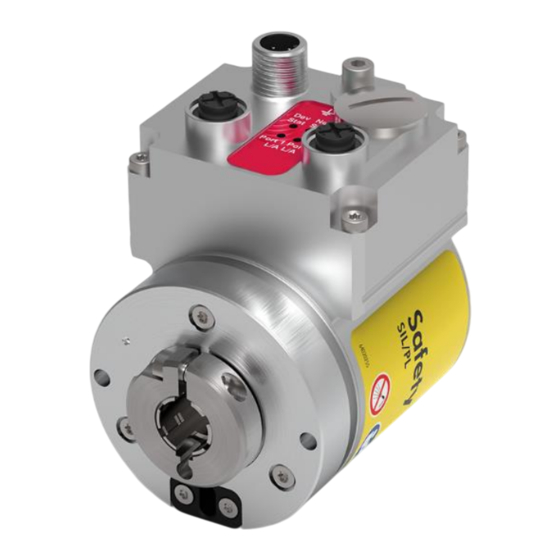
- Page 1 Original Absolute Encoder CD_582 EtherCAT/FSoE CDH582 / CDS582 CDV582 Images similar DIN EN 61508: SIL CL2 / SIL CL3 DIN EN ISO 13849: PL d / PL e _Safety information _Device-specific characteristics _Installation/Commissioning User Manual _Parameterization Interface _Error causes and solutions...
- Page 2 D-78647 Trossingen Eglishalde 6 Tel.: (0049) 07425/228-0 Fax: (0049) 07425/228-33 E-mail: info@tr-electronic.de www.tr-electronic.de Copyright protection This Manual, including the illustrations contained therein, is subject to copyright protection. Use of this Manual by third parties in contravention of copyright regulations is not permitted. Reproduction, translation as well as electronic and photographic archiving and modification require the written consent of the manufacturer.
-
Page 3: Table Of Contents
Contents Contents ........................3 Revision index ......................6 1 General information .................... 7 1.1 Applicability ..........................7 1.2 References ..........................8 1.3 Abbreviations and terms used ....................9 1.4 Main features .......................... 11 1.5 Principle of the safety function ....................12 2 Safety information .................... - Page 4 Contents 5.1.2.2 Safe preset value ..................32 Preset adjustment function ..................33 5.1.3.1 Timing diagram ..................34 5.2 NON-safety-related process data ................... 35 Input data ........................ 36 5.2.1.1 Status Bits (status byte) ................36 5.2.1.2 Position ...................... 37 5.2.1.3 Speed ......................37 Output data ......................
- Page 5 Object 6502h: Number of distinguishable revolutions ..........59 Object 6800h: FSoE Slave Frame Elements ............60 Object 6801h: FSoE Slave Frame Data (16 bit/32 bit) ........... 60 Object 7000h: FSoE Master Frame Elements ............61 Object 7001h: FSoE Master Frame Data (16 bit/32 bit) ......... 61 Object 8000h: FSoE parameter settings ...............
-
Page 6: Revision Index
Revision index Revision index Modification Date Index First release 05/29/2024 “Address correction” 08/14/2024 TR Electronic GmbH 2024, All Rights Reserved Printed in the Federal Republic of Germany Page 6 of 78 TR-ECE-BA-GB-0177 v03 08/14/2024... -
Page 7: General Information
The products are labeled with affixed nameplates and are components of a system. The following documentation therefore also applies: ● see chapter “Applicable documents” in the safety manual https://www.tr-electronic.de/f/TR-ECE-BA-GB-0142 ● Product data sheets https://www.tr-electronic.com/s/S026079 TR Electronic GmbH 2024, All Rights Reserved... -
Page 8: References
General information 1.2 References ETG.1000.1 – 6 EtherCAT Technology Group (ETG): EtherCAT specification ETG.1600, V1.0.4 EtherCAT Technology Group (ETG): Installation guideline ETG.5100, V1.2.0 EtherCAT Technology Group (ETG): Safety over EtherCAT, protocol specification ETG.5120, V1.3.0 EtherCAT Technology Group (ETG): Safety over EtherCAT, protocol extensions EN 50325:4 Industrial Communication Systems, based on ISO 11898 (CAN) for Controller Device Interfaces. -
Page 9: Abbreviations And Terms Used
1.3 Abbreviations and terms used Hexadecimal representation Explosion-proof enclosure 58 mm with integrated measuring system, A**582* all variants Controller Area Network. Data Layer Protocol for serial communication, described in ISO 11898. Category: Classification of cables which are also used for Ethernet. Absolute encoder with redundant dual scanning, all designs CAN in Automation. - Page 10 General information Continued Probability of Failure per Hour Operating mode with high requirement rate continuous demand. Probability of dangerous failure per hour. Service Data Object. Point to point communication with access to the object data list of a device. Safety Integrity Level: Four discrete levels (SIL1 to SIL4). The higher the SIL of a safety-related system, the lower the probability that the system cannot execute the required safety functions.
-
Page 11: Main Features
1.4 Main features ● EtherCAT - Interface with FSoE protocol, for transfer of a safe position and speed ● Fast process data channel over EtherCAT, not safety-oriented ● Only for variant 1: Additional incremental - / SIN/COS - or SSI - interface, not safety-oriented ●... -
Page 12: Principle Of The Safety Function
General information 1.5 Principle of the safety function System safety results when: – Each of the two scanning channels is largely fail-safe thanks to individual diagnostic measures – The measuring system internally compares the positions detected by both channels in two channels, also determines the speed in two channels and transfers the safe data in the FSoE frame via EtherCAT to the FSoE master –... -
Page 13: Safety Information
2 Safety information 2.1 Definition of symbols and notes means that death or serious injury will occur if the required precautions are not met. means that death or serious injury can occur if the required precautions are not met. means that minor injuries can occur if the required precautions are not met. -
Page 14: Safety Functions Of The Fail-Safe Processing Unit
Safety information 2.2 Safety functions of the fail-safe processing unit The measuring system does not make any decisions about valid states of motion of the system in which it is used. The system must check the consistency between the position information of the measuring system and the expected movement of the system. -
Page 15: Installation / Preparation For Commissioning
3 Installation / Preparation for Commissioning 3.1 Basic rules Deactivation of the safety function through conducted interference sources! All EtherCAT FSoE devices used on the bus must have an EtherCAT- and an FSoE-certificate. All safety-oriented devices must also have a certificate from a "Notified Body"... -
Page 16: Ethercat Transmission Technology, Cable Specification
Installation / Preparation for Commissioning Upon completion of installation, a visual inspection with report should be carried out. Wherever possible, the quality of the network should be verified using a suitable bus analysis tool. To ensure safe and fault-free operation, ETG.1600 EtherCAT Installation guideline IEC 60204-1 and the standards and directives referenced therein must be observed! -
Page 17: Connection Instructions
When the measuring system is delivered, a printed device-specific pin assignment form is enclosed. Download https://www.tr-electronic.com/service/downloads/pin-assignments.html The measuring system may be destroyed or damaged or its function be impaired by ingress of moisture! Connector plugs of the measuring system that are unused during storage and/or operation of the system have to be provided either with a mating connector or a protective cap. -
Page 18: Setting The Fsoe Address
Installation / Preparation for Commissioning 3.4 Setting the FSoE address Each FSoE slave device is addressed via a system-wide unique 16-bit safety address. However, the measuring system only supports an adjustable address range of eight bits: 1 to 255. The set safety address can be read out via “Object F980h: Safe address”. The measuring system may be destroyed or damaged or its function be impaired by penetration of foreign bodies and ingress of moisture! ... -
Page 19: Incremental Interface / Sin/Cos Interface (Optional)
3.5 Incremental interface / SIN/COS interface (optional) In addition to the EtherCAT – interface for outputting the absolute position, the measuring system can be equipped with an additional incremental interface. Adjustable parameter, see chapter “Object 2520h: ITF2_Incr_Parameter” on page 52. Alternatively, this interface can also be designed as a SIN/COS interface. -
Page 20: Signal Characteristics
Installation / Preparation for Commissioning Signal characteristics 1: Edge evaluation 2: Measuring system with 1024 pulses/revol. 3: Counter evaluation 1x: 1024 counter pulses/rev. 2x: 2048 counter pulses/rev. 4x: 4096 counter pulses/rev. Figure 2: Counter evaluation, incremental interface Measurement of signals tending to 0 V Differential measurement Figure 3: Level definition, SIN/COS interface... -
Page 21: Htl/Ttl Level (Optional)
HTL/TTL Level (optional) Optionally, the incremental interface is also available with HTL and TTL levels. For technical reasons, the user using this version has to take the following general conditions into account: ambient temperature, cable length, cable capacitance, supply voltage, and output frequency. In this case, the maximum output frequencies that can be reached via the incremental interface are a function of the cable capacitance, the supply voltage and the ambient temperature. - Page 22 Installation / Preparation for Commissioning Figure 5: Cable lengths / limit frequencies, HTL version Other cable parameters, frequencies and ambient temperatures as well as bearing heat and temperature increase via the shaft and flange, can yield a considerably poorer result in practice. Therefore, the fault-free function of the incremental interface with the application-dependent parameters has to be checked prior to productive operation.
-
Page 23: Ssi Interface (Optional)
3.6 SSI interface (optional) Instead of the incremental interface, the measuring system can be optionally equipped with a synchronous serial absolute SSI interface in addition to the EtherCAT – interface. Adjustable parameters, see chapter “Object 2500h: ITF2_SSI_Parameter” on page 49. This additional interface is not evaluated in relation to safety and may not be used for safety instrumented purposes! ... - Page 24 Installation / Preparation for Commissioning Monoflop time Clock+ Data+ Figure 6: Typical SSI transmission sequences High Clock+ High Data+ High internal Monoflop, can be retriggered Figure 7: SSI transmission format TR Electronic GmbH 2024, All Rights Reserved Printed in the Federal Republic of Germany Page 24 of 78 TR-ECE-BA-GB-0177 v03 08/14/2024...
-
Page 25: Cable Length
Cable length The maximum cable length depends on the SSI clock frequency and cable quality. TR’s own hybrid cable (part number: 64-200-021) was used for the measurements. SSI clock frequency [kHz] 2000 1000 Cable length [m] ca.12,5 ca. 25 ca. 50 ca. -
Page 26: Commissioning
The XML file is integrated by the EtherCAT network configuration tool in order to properly configure and commission the measuring system. Download ● www.tr-electronic.de/f/TR-ECE-ID-MUL-0081 TR Electronic GmbH 2024, All Rights Reserved Printed in the Federal Republic of Germany Page 26 of 78... -
Page 27: Bus Status Display
4.3 Bus status display Destruction, damage and malfunction of the measuring system due to penetration of foreign bodies and moisture! Securely seal the access to the LEDs again with the screw plug after completing the settings. LED1: FSoE Status (green/red) LED2: Net Run (green) -
Page 28: Led1, Fsoe Status
Commissioning LED1, FSoE Status green Description Initialization, device off Single flash INIT state, booting Data state – output of safe data Double flash Data state – output of process data Description Single flash Error acknowledgement required by the user System or safety error For appropriate measures in case of error, see chapter “Troubleshooting and Diagnosis Options”, page 73. -
Page 29: Structure Of Process Data
5 Structure of Process Data 5.1 Safety-oriented process data Via the FSoE master, the safety-related process data can optionally be mapped or hidden in the input and output process data (mapping objects 0x1A00/0x1600). There are two modules for the safety slot: - Standard FSoE module - FSoE 16bit module for transmission of 16-bit values. -
Page 30: Input Data
Structure of Process Data Input data 5.1.1.1 SafeStatus ● Danger of death, serious physical injuries and/or damage to property due to uncontrolled start-up of the drive system, in the event of NON- evaluation of Safe state bit 2 The output actual values are only valid if Safe state bit 2 = 1. -
Page 31: Safe Absolute Position
5.1.1.2 Safe absolute position Actual value scaled, UNSIGNED32 Byte 7 – 0 15 – 8 23 – 16 31 – 24 – 2 – 2 – 2 – 2 Data The current scaled actual position is output via the Safe absolute position register. The output position is not signed. -
Page 32: Output Data
Structure of Process Data Output data 5.1.2.1 SafeControl UNSIGNED16 Byte 7 – 0 15 – 8 – 2 – 2 Data Description Safe preset preparation The bit is used to prepare the preset adjustment function. The actual preset can only be executed via the Safe preset request control bit if this bit is set. -
Page 33: Preset Adjustment Function
Preset adjustment function ● Danger of death, serious physical injury and/or damage to property due to uncontrolled start-up of the drive system during execution of the preset adjustment function! The relevant drive systems must be locked to prevent automatic start-up ... -
Page 34: Timing Diagram
Structure of Process Data 5.1.3.1 Timing diagram blue area: Output signals FSoE Master -> measuring system orange area: input signals measuring system -> FSoE master TR Electronic GmbH 2024, All Rights Reserved Printed in the Federal Republic of Germany Page 34 of 78 TR-ECE-BA-GB-0177 v03 08/14/2024... -
Page 35: Non-Safety-Related Process Data
5.2 NON-safety-related process data The FSoE master can be used to display or remove the NON-safety-related process data in the input and output process data (mapping objects 0x1A01/0x1601). Structure of the input data Byte Input data Data type Object description Status Bits UNSIGNED8 0x3010, see page 54... -
Page 36: Input Data
Structure of Process Data Input data 5.2.1.1 Status Bits (status byte) UNSIGNED8 Byte 7 – 0 – 2 Data Description Adjustment OK 1: Adjustment has been executed Output of the original position 0: own channel in error state 1: Output of the original position, either ->... -
Page 37: Position
5.2.1.2 Position Actual value scaled, UNSIGNED32 Byte 7 – 0 15 – 8 23 – 16 31 – 24 – 2 – 2 – 2 – 2 Data The current scaled actual position is output via the Position register. The output position is not signed. 5.2.1.3 Speed Speed, INTEGER32 Byte... -
Page 38: Output Data
Structure of Process Data Output data 5.2.2.1 Control Bits (control byte) / Preset adjustment function Danger of physical injury and damage to property due to an actual value jump during execution of the preset adjustment function! The adjustment function should only be executed when the measuring system is at a standstill, or the resulting actual value jump must be permitted by the program and the application! UNSIGNED8... -
Page 39: Ethercat - Object Directory
6 EtherCAT – Object Directory Both NON-safety-oriented and the safety-oriented data packed in safety frames are transferred via the objects in the EtherCAT directory. However, the use of safety-oriented data in the non-safety-oriented control is not safe for the purposes of a safety standard. The overall management occurs via the NON-safety-oriented control section. -
Page 40: Manufacturer-Specific Objects
EtherCAT – Object Directory 6.2 Manufacturer-specific objects Index (h) Object Name Data length Attr. Page Parameter grey 2040 RECORD UNSIGNED16 (NON-safety-oriented) TRDiagV2 2200 ARRAY OCTET STRING (internal purposes) 2220 Failsafe Simulation UNSIGNED8 2500 RECORD ITF2_SSI_Parameter UNSIGNED8 2520 RECORD ITF2_Incr_Parameter UNSIGNED8 2707 ARRAY Firmware-Info... -
Page 41: Object 2040H: Parameter Grey
Object 2040h: Parameter grey The object contains all NON-safety-related configuration parameters. Index Sub Comment Default [Unit] Type Attr. Page Max. Subindex UNSIGNED8 Rotational direction grey True [increasing] BOOL Measuring range grey 536870912 [Steps] UNSIGNED32 Revolutions numerator 65536 UNSIGNED32 grey [Revol. Numerator] Revolutions denominator UNSIGNED32 grey... -
Page 42: Subindex 2, 3, 4: Scaling Parameters
EtherCAT – Object Directory 6.2.1.2 Subindex 2, 3, 4: Scaling parameters Risk of physical injury and material damage due to shifting of the zero point when the measuring system is switched on again after positioning in de-energized state! If more than 32767 revolutions are executed in de-energized state, the zero point of the multiturn measuring system may be lost! ... - Page 43 Subindex 3: REVOLUTIONS NUMBERATOR / Subindex 4: REVOLUTIONS DENOMINATOR These two parameters together define the number of revolutions, before the measuring system starts at 0 again. As decimal numbers are not always finite (as is e.g. 3.4), but they may have an infinite number of digits after the decimal point (e.g.
- Page 44 EtherCAT – Object Directory The following example serves to illustrate the approach. Given: ● Measuring system with 4096 steps/rev. and max. 4096 revolutions ● Resolution 1/100 mm ● Make sure that the measuring system is programmed in its full resolution and measuring range (4096x4096): Measuring range in steps = 16777216,...
-
Page 45: Subindex 5: Speed Format Grey
6.2.1.3 Subindex 5: Speed format grey Subindex 5 indicates the resolution at which the speed is calculated and output. The speed is output signed, as a two's complement: ● Counting direction setting = increasing – Output positive, with clockwise rotation (looking at flange connection) ●... -
Page 46: Subindex 7: Speed Integration Time Grey
EtherCAT – Object Directory 6.2.1.5 Subindex 7: Speed integration time grey Subindex 7 indicates the integration time in [ms] for the parameter Subindex 5: Speed format grey, see page 45. The parameter serves to calculate the speed, which is output via the cyclic process data. The speed is Steps/Integration time. -
Page 47: Subindex 8: Speed Filter Intensity Grey
6.2.1.6 Subindex 8: Speed filter intensity grey The output speed can be averaged using the Speed filter intensity grey parameter. The averaging strength can be preset. You can also select whether the filtering is dynamically switched off in acceleration phases, see Speed filter type grey parameter described below. This means that the speed signal can quickly follow the actual course in the event of changes and is stable in the stationary range. -
Page 48: Subindex 11: Parameter Coupled To Safe
EtherCAT – Object Directory 6.2.1.9 Subindex 11: Parameter coupled to safe BOOL Value Assignment Description Default 0 = false Function switched off The setting Parameter coupled to safe = on can be used to specify whether the NON-safety-related process data channel Grey should be coupled with the safety-related process data channel FSoE. -
Page 49: Option: Second Interface
OPTION: Second interface 6.2.3.1 Object 2500h: ITF2_SSI_Parameter The measuring system can optionally be equipped with a synchronous-serial absolute SSI interface, in addition to the fieldbus interface. SSI data transmission format: Position Status Sign of life Checksum max. 8…29 bits max. 0…2 bits max. -
Page 50: Subindex 3: Ssi_Databits
EtherCAT – Object Directory 6.2.3.1.3 Subindex 3: SSI_Databits The SSI_Databits subindex defines the number of reserved bits for the measuring system position, and the number of required SSI clock pulses to the LSB of the data is also specified. Special bits such as status bits, sign-of-life bits or checksum bits are not included and are output in this order after the data bits. -
Page 51: Subindex 6: Ssi_Lifecounterbits
6.2.3.1.6 Subindex 6: SSI_Lifecounterbits The SSI_Lifecounterbits subindex defines the number of reserved bits for the sign-of-life output. The sign-of-life counter is incremented depending on the scanning processes and inserted into the SSI telegram. Monitoring of this incrementation by the control ensures that the newly transferred position value originates from a current scanning process. -
Page 52: Object 2520H: Itf2_Incr_Parameter
EtherCAT – Object Directory 6.2.3.2 Object 2520h: ITF2_Incr_Parameter The measuring system can optionally be equipped with an incremental interface, in addition to the fieldbus interface. Index Subindex Comment Default Type Attr. Largest subindex supported UNSIGNED8 2520h Pulses per revolution 0: 1024 pulses UNSIGNED8 6.2.3.2.1 Subindex 1: Incr_Steps The Incr_Steps subindex defines the number of pulses per revolution. -
Page 53: Object 2736H: Update Time
Object 2736h: Update time The object contains the update time of the measuring system. Index 0x2736 Description Update time Data type UNSIGNED32 Access PDO mapping Value contains the seconds since Jan. 1. 1970 (UNIX time) Object 2738h: Update history The object contains the update history of the measuring system. Index 0x2738 Description... -
Page 54: Object 3001H: Cycle Time Bus
EtherCAT – Object Directory Object 3001h: Cycle time bus The current EtherCAT bus cycle time is output via the object. Index 0x3001 Description Cycle time bus Data type UNSIGNED32 Access PDO mapping Unit µs Object 3002h: Cycle time encoder The current internal measuring system cycle time is output via the object. Index 0x3002 Description... -
Page 55: Object 3011H: Speed
Object 3011h: Speed The current speed is output via the object and is part of the NON-safety-related process data, see from page 35. Index 0x3011 Description Speed Data type INTEGER32 Access PDO mapping –2147483648 Lower limit Upper limit +2147483647 Unit Increments / Integration time unsafe Can only be accessed via the process data. -
Page 56: Object 3100H: Control Bits
EtherCAT – Object Directory Object 3100h: Control bits The object contains the control byte for the preset adjustment function and is part of the NON- safety- related process data, see from page 35. Index 0x3100 Description Control byte Data type UNSIGNED8 Access PDO mapping... -
Page 57: Profile Specific Objects
6.3 Profile specific objects Index (h) Object Name Attr. Page 6000 Operating parameters 6004 Position value 6500 Operating status 6501 Single turn resolution 6502 Number of distinguishable revolution 6800 RECORD FSoE Slave Frame Elements 6801 RECORD FSoE Slave Frame Data 7000 RECORD FSoE Master Frame Elements 7001... -
Page 58: Object 6000H: Operating Parameters
EtherCAT – Object Directory Object 6000h: Operating parameters The object with index 6000h only contains the measuring system operating parameter for the switching of the counting direction. Index 0x6000 Description Operating parameters Data type UNSIGNED16 Object code VARIABLE Access PDO mapping Default Function Bit = 0... -
Page 59: Object 6500H: Operating Status
Object 6500h: Operating status This object provides the operating status of the measuring system functions configured in Object 6000h: Operating parameters. However, only the function for switching the counting direction is supported. Index 0x6500 Description Operating status Data type UNSIGNED16 Object code VARIABLE Access... -
Page 60: Object 6800H: Fsoe Slave Frame Elements
EtherCAT – Object Directory Object 6800h: FSoE Slave Frame Elements The object is required to describe the complete FSoE slave frame in the TxPDO mapping object 0x1A00 together with “Object 6801h: FSoE Slave Frame Data (16 bit/32 bit)”. Index Subindex Comment Type Attr. -
Page 61: Object 7000H: Fsoe Master Frame Elements
Object 7000h: FSoE Master Frame Elements The object is required to describe the complete FSoE master frame in the RxPDO mapping object 0x1600 together with “Object 7001h: FSoE Master Frame Data (16 bit/32 bit)”. Index Subindex Comment Type Attr. 7000h Number of entries = 5 UNSIGNED8 FSoE Master Command... -
Page 62: Object 8000H: Fsoe Parameter Settings
EtherCAT – Object Directory Object 8000h: FSoE parameter settings The object contains all safety-related configuration parameters. Index Comment Default [Unit] Type Attr. Page 8000h Number of entries UNSIGNED8 SIL Level UNSIGNED8 Rotational direction true [increasing] BOOL Measuring range 536870912 [Steps] UNSIGNED32 Revolutions numerator 65536 [Rev. -
Page 63: Subindex 2: Rotational Direction
6.3.10.2 Subindex 2: Rotational direction Danger of death, serious physical injury and/or damage to property due to a jump of the absolute value following a change in the rotational direction function! The internal calculation algorithm produces different absolute positions for the counting direction settings decreasing or rising. - Page 64 EtherCAT – Object Directory Via the scaling parameters - Subindex 3 - Measuring range - Subindex 4 - Revolutions numerator - Subindex 5 - Revolutions denominator the physical resolution of the measuring system can be changed. The measuring system supports the gear function for round axes.
- Page 65 Formula for gearbox calculation: Number of numerator revolutions Measuring range in steps = number of steps per revolution * Number of denominator revolutions If it is not possible to enter parameter data in the permitted ranges of numerator and denominator, the attempt must be made to reduce these accordingly.
- Page 66 EtherCAT – Object Directory Derived: Number of revolutions covered = 607682 steps / 4096 steps/rev. = 148.3598633 revolutions Number of mm / revolution = 2000 mm / 148.3598633 revs. = 13.48073499mm / rev. For 1/100mm resolution this equates to a number of steps / revolution of 1348.073499 required programming: Number of numerator revolutions = 4096...
-
Page 67: Subindex 6: Speed Format
6.3.10.4 Subindex 6: Speed format Subindex 6 indicates the resolution at which the speed is calculated and output. The speed is output signed, as a two's complement: ● Counting direction setting = ascending – Output positive, with clockwise rotation (looking at flange connection) ●... -
Page 68: Subindex 8: Speed Integration Time
EtherCAT – Object Directory 6.3.10.6 Subindex 8: Speed integration time Subindex 8 indicates the integration time in [ms] for the parameter Subindex 6: Speed format, see page 67. The parameter serves to calculate the speed, which is output via the cyclic process data. The speed is steps/integration time. -
Page 69: Subindex 9: Speed Filter Intensity
6.3.10.7 Subindex 9: Speed filter intensity The output speed can be averaged using the Speed filter intensity parameter. The averaging strength can be preset. You can also select whether the filtering is dynamically switched off in acceleration phases, see Speed filter type parameter described below. This means that the speed signal can quickly follow the actual course in the event of changes and is stable in the stationary range. -
Page 70: Subindex 11: Window Increments
EtherCAT – Object Directory 6.3.10.9 Subindex 11: Window increments This parameter defines the maximum permissible position deviation in increments of the master / slave scanning systems integrated into the measuring system. The permissible tolerance window is basically dependent on the maximum speed occurring in the system and must first be determined by the system operator. -
Page 71: Resetting The Device Parameters
7 Resetting the device parameters Destruction, damage and malfunction of the measuring system due to penetration of foreign bodies and moisture! Make sure that the screw plug is securely closed again after accessing the address switches to make settings. Resetting of the device parameters is carried out using two HEX rotary switches SW1 (16 ) and SW2 (16... -
Page 72: Output Of Safe Data (Substitute Values)
Output of safe data (substitute values) 8 Output of safe data (substitute values) The safety function requires, that in the case of an error in the safety-oriented safety channel, instead of the cyclically output values the safe data (0) are used in the following cases (FailSafeData). ●... -
Page 73: Troubleshooting And Diagnosis Options
9 Troubleshooting and Diagnosis Options 9.1 Optical displays For assignment and position of the status LEDs, see chapter “Bus status display” on page 27. Link / Activity LEDs green LED Cause Solution - Check power supply, wiring Voltage supply absent or too low - Is the voltage supply in the permissible range? No Ethernet connection... - Page 74 Troubleshooting and Diagnosis Options red LED Cause Solution Measuring system waits for an error acknowledgement. Reset the error via bit 2 SafeStatus bits: Single flash Error acknowledge in the - Error acknowledge (green = OFF) SafeControl control word, see page 32. requested = 1 - Safe state = 0 To be able to restart the measuring...
-
Page 75: Error Acknowledgement - Flow Diagram
9.2 Error acknowledgement – flow diagram When the measuring system detects a safety-relevant error, it automatically switches from process data output to the FailSafeData state. If the error is eliminated and the error type permits restarting, the measuring system automatically switches back to process data output. However, the Safe State bit remains at "0"... -
Page 76: Manufacturer-Specific Diagnosis Ethercat (Object)
Troubleshooting and Diagnosis Options 9.3 Manufacturer-specific diagnosis EtherCAT (object) The measuring system supports the following manufacturer-specific diagnosis object: Index Subindex Comment Type Attr. 2200h No. of entries UNSIGNED8 Manufacturer-specific diagnosis OCTET STRING Manufacturer-specific diagnosis OCTET STRING Manufacturer-specific diagnosis OCTET STRING …... -
Page 77: Checklist, Part 2 Of 2
10 Checklist, Part 2 of 2 We recommend that you print out and work through the Checklist for commissioning, when replacing the measuring system and when changing the parameterization of a previously accepted system and store it as part of the overall system documentation. Documentation basis Date Edited... -
Page 78: Appendix
Appendix 11 Appendix 11.1 TÜV certificate Download, CD_582M +FS02 www.tr-electronic.de/f/TR-ECE-TI-DGB-0344 Download, CD_582M +FS03 www.tr-electronic.de/f/TR-ECE-TI-DGB-0350 11.2 EtherCAT certificate Download www.tr-electronic.de/f/TR-ECE-TI-GB-0414 11.3 Safety over EtherCAT certificate Download www.tr-electronic.de/f/TR-ECE-TI-GB-0413 11.4 EU Declaration of Conformity Download, FS02 www.tr-electronic.de/f/TR-ECE-KE-DGB-0354 Download, FS03 www.tr-electronic.de/f/TR-ECE-KE-DGB-0358 TR Electronic GmbH 2024, All Rights Reserved...
Need help?
Do you have a question about the CD 582 Series and is the answer not in the manual?
Questions and answers